


XTP T UWP 302 • Installation and Operation 7
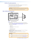
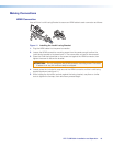
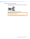
b RS-232 Over XTP port — To pass bidirectional serial or other control signals between
XTP-compatible devices, connect a control device to the 5-pole captive screw
connector. The port includes only the 3 poles labeled “RS-232.”
IR Over XTP port — To transmit and receive IR signals (up to 40 kHz), connect a
control device to the 5-pole captive screw connector. This port includes only the 2 poles
labeled “IR” and shares the ground pole with the RS-232 port.
NOTE: RS-232 and IR data can be transmitted simultaneously (see
RS-232 and IR Over XTP Communication on page 12 for wiring details).
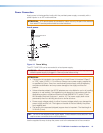
c Remote RS-232 connector — Connect a host device to the 3.5 mm, 3-pole captive
screw connector for serial control of the transmitter.
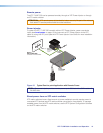
d Power connector — Connect an external power supply to the 2-pole captive screw
connector. The Power LED lights to indicate the device is receiving power.
NOTE: The XTP T UWP 302 can also be powered remotely (see Power
Connection on page 13).
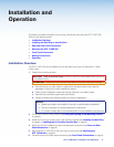
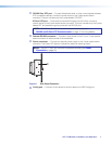
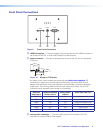
CONFIG
RESET
e
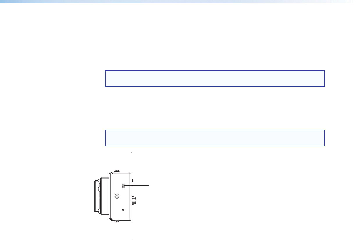
Figure 6. Side Panel Connector
e
Config port — Connect a host device to the front panel mini USB Config port.