


TeamPoS 3000 XL and XL
2
Installation
D900000145 Issue 3 5-55
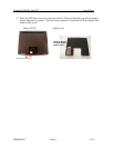
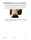
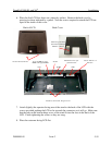
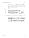
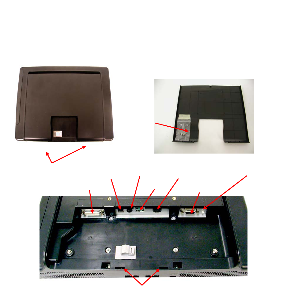
6. Place the first LCD face down on a clean dry surface. Remove the back cover by
pressing in where indicated by symbol. Note the screws required to attach the LCD are
taped to the inside of this cover.
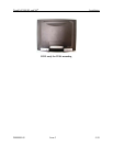
Back of LCD Back Cover
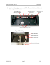
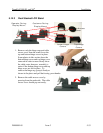
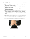
7. Attach (lightly) the operator facing arm of the stand to the back of the LCD with the
screws provided pushing the LCD as far towards the connectors as it will go. Make sure
that the tabs on the bottom hinge cover of the stand fit into the slots in the back of the
LCD. Finish tightening the screws so they are snug.
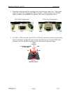
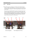
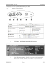
8. Place the customer facing LCD flat
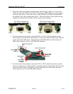
Press Here and Lift
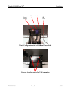
Mounting Screws
Panhead, Phillips
M3x0.5 x 8mm
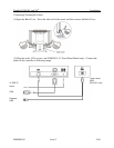
DVI
VGA
A to B USB for opt.
MSR or Keypad MSR
Audio
pUSB
LCD Power for opt.
power brick
Touch Panel 1-2
Switch
Notches for lower hinge cover