


TeamPoS 3000 XL and XL
2
Installation
D900000145 Issue 3 5-39
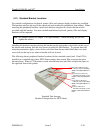
5.13. Standard Bracket Locations
For stacked configurations, keyboard, printer, filler and operator display brackets are available.
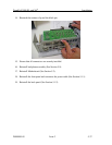
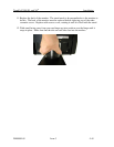
The brackets attach to the top of the control unit and restrain the peripherals from sliding. When
installing the peripheral brackets, install each bracket using the two screws that have been
provided with the bracket. For most stacked installations keyboard, printer, filler and display
brackets will be required.
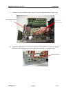
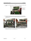
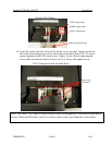
Installing the brackets requires placing the bracket on the appropriate screw holes on the top of
the chassis and securing with the two screws provided for each bracket. To prevent dust and
moisture penetration, apply a screw-hole cover label from the provided label sheet over each
screw hole on the top cover where a bracket will not be used.
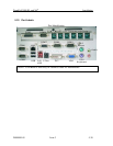
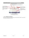
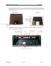
The following shows peripheral bracket locations for the standard control unit. If an LCD is
installed on a standard unit with a DT50 Series printer, then central filler occupies the space
between them. When a CT10 printer is used, an additional two-part filler occupies the space to
the right and front of the printer.
Standard Unit showing
Bracket Configuration for DT50 Series
Stacked LCD Brackets
4 Screws, Pan head phillips,
SEMS, nickel plated M3x0.5 x
8mm
Central Filler Bracket
2 Screws, Flat head, C-sink,
Phillips, nickel plated M3x0.5 x
8mm
DT50 Series Bracket
2 Screws, Pan head, Phillips,
SEMS, nickel plated M3x0.5 x
10mm
Keyboard Bracket
2 Screws, Flat head, C-sink,
Phillips, nickel plated M3x0.5 x
8mm
Note: See bracket options in Chapter 11 for part numbers. When installing, do not over-
tighten the screws.