


TeamPoS 3000 XL and XL
2
Maintenance
D900000145 Issue 3 7-57
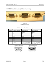
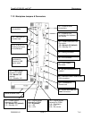
7.13 Replacing the Backplane
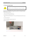
Caution: Be sure to observe all ESD precautions and power off procedures.
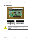
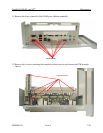
The backplane assembly contains the power supply and I/O boards. The backplane PCB is
spared as an individual board and requires removal of the power supply and I/O boards before
removing the screws attaching the PCB to the assembly.
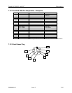
Note: Before installing the new docking plane be sure to set the jumper switches as indicated in
the Docking Backplane Jumper Settings table at the end of this section.
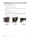
1. Looking from the rear, the power supply is on the right.
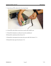
2. Remove the rear panel (See Section 5.1.2).
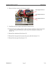
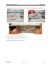
3. Disconnect the power cable from the controller.
4. Remove the front panel (See Section 5.1.1).The yellow LED should be off (See Section 1.2).
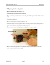
5. Unseat the motherboard assembly.
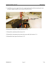
6. At the rear, remove the locking screw on the right hand side of the backplane.