216 Upgrade and Maintenance Manual MX130 S2
System board and components
Ê Remove eight screws from the system board (see circles) beginning with the
two centering bolts (C).
Figure 136: Detaching the system board (B)
V CAUTION!
– Do not lift or handle the system board by any of its heat sinks!
– Ensure not to damage the EMI springs to comply with applicable
EMC regulations and satisfy cooling requirements and fire protection
measures.
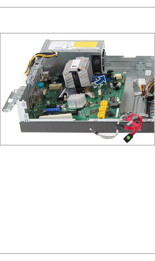
Ê Hold the defective system board by the memory module ejectors and a PCI
slot and shift the system board to the right until the plug shells disengage
from the cut-outs in the connector panel and lift it out of the chassis.
Ê If applicable, remove the TPM board as described in section "Trusted
Platform Module (TPM)" on page 204.
Ê Remove the processor heat sink and the processor as described in section
"Replacing the processor" on page 191.


