


GE Energy
D400 Substation Data Manager User's Manual 33
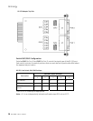
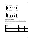
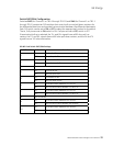
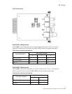
Switch SW3/SW4 Configuration
Switches SW3 (for Channel 2 on TB1-6 through TB1-10) and SW4 (for Channel 1 on TB1-1
through TB1-5) contain ten DIP-switches that control pull-up and pull-down resistors for
the differential data lines and provide line termination between the differential data pairs.
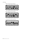
Each DIP-switch can be set to ON or OFF to select the appropriate function for the switch.
That is, if all pins are set to ON, switch is ON. If all pins are set to OFF, switch is OFF.
If termination/pull up is selected, the TX+ and RX+ signals have a 680 ohm pull-up
resistor, the TX- and RX- signals have a 680 ohm pull-down resistor, and the RX and TX
signals have a 120 ohm termination.
RS-485 Card Switch SW3/SW4 Settings
SW3/SW4 Pin Pin Position Function
ON Pull-up for TX+
1
OFF No pull-up for TX+
ON Pull-down for TX-
2
OFF No pull-down for TX-
3 Not connected
ON Pull-up for RX+
4
OFF No pull-up for RX+
ON Pull-down for RX-
5
OFF No pull-down for RX-
ON Line termination between TX+ and TX-
6
OFF No Line termination between TX+ and TX-
ON Line termination between TX+ and TX-
7
OFF No Line termination between TX+ and TX-
8 Not connected
ON Line termination between RX+ and RX-
9
OFF No Line termination between RX+ and RX-
ON Line termination between RX+ and RX-
10
OFF No Line termination between RX+ and RX-