


GE Energy
62
994-0089–1.00–2, General
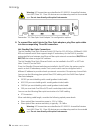
4.10 Front Maintenance Port
The serial communications port on the front panel of the D400 provides a local
connection with the D400 to perform the initial setup of the D400 and to carry out
maintenance and diagnostic procedures. The front maintenance port provides a direct
serial connection to a PC using a serial null modem cable (GE Part No. 977-0529/72),
which is supplied with the D400.
See section “6.1 Connecting to the D400 for the First Time” for more information on
setting up communications with the D400.
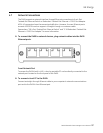
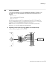
» To connect your computer to the D400:
Connect the supplied serial null modem cable (GE Part No. 977-0529/72) to your
computer’s serial communications port and to the D400's front communications port.
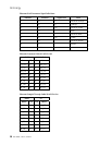
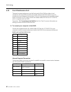
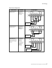
D400 Front Serial Port DB-9 Pin Out
Pin # Signal
1 DCD
2 RX Data
3 TX Data
4 DTR
5 GND
6 DSR
7 RTS
8 CTS
9 Not Connected
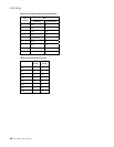
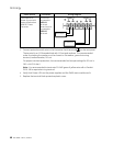
Minimal Required Connection
The minimal cable connection required to establish successful communication between
your PC and the D400 is as follows:
PC Pin # D400 Pin # Signal
9-Pin Female
9-Pin Female
(w/o Converter)
2 3 TX
3 2 RX
5 5 GND