


GE Energy
D400 Substation Data Manager User's Manual 55
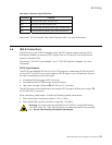
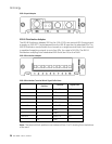
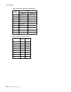
Fiber Optic Connector Signal Definitions
Connector Function
TX1 Primary Fiber Optic Transmit Port
RX1 Primary Fiber Optic Receive Port
TX2 Hot Standby Secondary Fiber Optic Transmit Port
RX2 Hot Standby Secondary Fiber Optic Receive Port
See section “3.9 Hot Standby Fiber Optic Ethernet Switch” for more information.
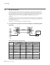
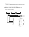
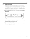
4.6 IRIG-B Connections
The D400 uses a pair of IRIG-B adapter cards, the IRIG-B Input Adapter and the IRIG-B
Distribution Adapter, to accept an IRIG-B signal from a GPS receiver then distribute the
signal to connected IEDs.
See sections “3.6 IRIG-B Input Adapter” and “3.7 IRIG-B Distribution Adapter” for more
information.
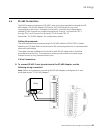
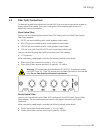
IRIG-B Input Adapter
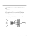
The IRIG-B Input Adapter (GE Part No. 520-0211) plugs into a dedicated IRIG-B slot (slot 9)
on the D400. The IRIG-B Input card accepts an IRIG-B signal in one of three input formats
through a corresponding connector type:
• Modulated IRIG-B through a BNC connector
• Demodulated IRIG-B (TTL) through a terminal block
• Fiber Optic through a Receive (RX) 820-850 nm ST connector
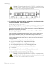
The IRIG-B signal can be distributed to an attached IED through the fiber optic output (TX)
on 820-850 nm ST connector.
When calculating cable length, consider the following optical power levels:
• Glass optical fiber transmitter power is –19.0 ± 2 dBm
• Glass optical fiber receiver sensitivity is typically –25.4 dBm
Warning: LED transmitters are classified as IEC 60825-1 Accessible Emission
Limit (AEL) Class 1M. Class 1M devices are considered eye safe to the unaided
eye. Do not view directly with optical instruments.