


GE Energy
D400 Substation Data Manager User's Manual 53
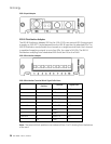
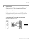
4.5 Fiber Optic Connections
For devices located some distance from the D400, they may be connected using glass or
plastic optical fiber cables. Fiber optic cabling also offers superior performance in
electrically noisy environments.
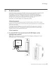
Glass Optical Fiber
You can use the following glass optical fiber (GOF) cabling with the D400 Glass Optical
Fiber Serial adapter:
• 50/125 µm core/cladding multi-mode (gradient index) cable
• 62.5/125 µm core cladding multi-mode (gradient index) cable
• 100/140 µm core/cladding multi-mode (gradient index) cable
• 200 µm core Hard-Clad Silica (HCS) multi-mode (step index) cable
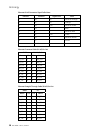
You can use the following fiber optic terminations for D400 cabling:
• ST Connectors
When calculating cable length, consider the following optical power levels:
• Glass optical fiber transmitter power is –19.0 ± 2 dBm
• Glass optical fiber receiver sensitivity is typically –25.4 dBm
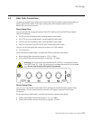
Warning: LED transmitters are classified as IEC 60825-1 Accessible Emission
Limit (AEL) Class 1M. Class 1M devices are considered eye safe to the unaided
eye. Do not view directly with optical instruments.
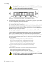
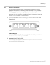
Plastic Optical Fiber
You can use 1 mm plastic optical fiber (POF) cabling with the D400 Plastic Optical Fiber
Serial adapter. The recommended termination is the Agilent Versatile Link Simplex
Connector.
When calculating cable length, consider the following optical power levels:
• Plastic optical fiber transmitter power is –9.0 ± 4.5 dBm
• Plastic optical fiber receiver sensitivity is typically –39 dBm