


GE Energy
34
994-0089–1.00–2, General
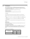
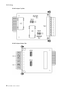
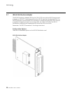
3.5 Fiber Optic Serial Adapter
The Fiber Optic Serial Adapter is available in two variants:
• Glass Optical Fiber (GOF) Serial with 820-850 nm ST connectors
(GE Part No. 520-0209)
• Plastic Optical Fiber (POF) Serial with 660 nm Agilent Versatile Link connectors (GE
Part No. 520-0210)
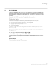
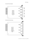
The Fiber Optic Serial cards include two pairs of channels for signal transmission
(TX1/TX2) and reception (RX1/RX2) through ST or Versatile connectors. The cards plug into
any serial communication slot (slots 1 through 8) on the D400.
See section “4.5 Fiber Optic Connections” for typical cable connections.
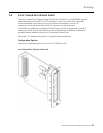
Configuration Options
The Fiber Optic Serial card supports the following configuration options for each channel:
• Standard state
• Inverted state
The state for each channel is selectable via a single two-position pin switch SW1 on the
Fiber Optic Serial card.
Follow instructions for setting the switch to select the appropriate state for each channel.
Note: The fiber optic channel settings on the D400 must match the set up of the other
end of the fiber optic communications channel.
Factory Default
The factory default setting is Standard state on each channel.
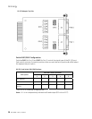
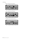
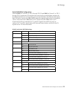
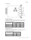
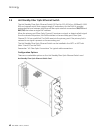
Switch SW1 Configuration
Switch SW1 controls the state of each fiber optic channel. The switch contains four two-
position pins that can each be set to A or B to select the appropriate state.
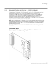
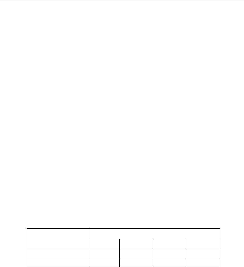
Fiber Optic Serial Card Switch SW1 Settings
SW1 Switch Positions
State Option
1 2 3 4
Standard (default) B A B A
Inverted A B A B
Note: In Standard state fiber is lit when a “1” is transmitted. In Inverted state fiber is lit
when a “0” is transmitted.