


GE Energy
54
994-0089–1.00–2, General
Warning: LED transmitters are classified as IEC 60825-1 Accessible Emission
Limit (AEL) Class 1M. Class 1M devices are considered eye safe to the unaided
eye. Do not view directly with optical instruments.
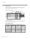
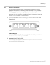
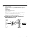
See section “3.5 Fiber Optic Serial Adapter” for configuration options.
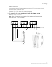
» To connect fiber optic links to the Fiber Optic adapters, plug fiber optic cables
into the corresponding TX and RX connectors.
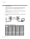
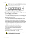
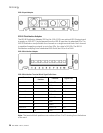
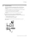
Hot Standby Fiber Optic Connections
The Hot Standby Fiber Optic Ethernet Switch (GE Part No. 520-0214) is a 100BaseSX (820-
850 nm) network switch that supports single-IP redundancy for the D400. It provides
automated fail over between two Ethernet fiber optic network connections (RX1/TX1 and
RX2/TX2) that share a single MAC address.
The Hot Standby Fiber Optic Ethernet Switch can be installed in the NET1 or NET2 slot
(slots 11 and 12) on the D400.
If two Hot Standby Ethernet switches are installed in the NET slots, the system may be
used in a dual-IP redundancy mode. That is, each switch can be configured with a
different IP address to provide a back up network connection if the primary channel fails.
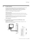
You can use the following glass optical fiber (GOF) cabling with the D400 Glass Optical
Fiber Serial adapter:
• 50/125 µm core/cladding multi-mode (gradient index) cable
• 62.5/125 µm core cladding multi-mode (gradient index) cable
• 100/140 µm core/cladding multi-mode (gradient index) cable
• 200 µm core Hard-Clad Silica (HCS) multi-mode (step index) cable
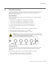
You can use the following fiber optic terminations for D400 cabling:
• ST Connectors
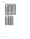
When calculating cable length, consider the following optical power levels:
• Glass optical fiber transmitter power is –19.0 ± 2 dBm
• Glass optical fiber receiver sensitivity is typically –31.0 dBm
Warning: LED transmitters are classified as IEC 60825-1 Accessible Emission
Limit (AEL) Class 1M. Class 1M devices are considered eye safe to the unaided
eye. Do not view directly with optical instruments.