


GE Energy
46
994-0089–1.00–2, General
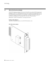
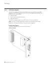
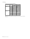
4.2 Cabling Overview
The D400 provides a series of I/O adapter cards for connecting cables and wiring from
substation devices and network interfaces. All physical connections are made to easily
accessible connectors on the rear panel of the D400.
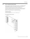
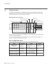
D400 Field and Network Connections
Slot 1
Slot 2
Slot 3
Slot 4
Slot 5
Slot 6
Slot 7
Slot 8
Slot 9
Slot 10
Slot 11
Slot 12
Slot 13
Serial Communication Slots
IRIG-B Input Slot
IRIG-B Distribution Slot Network Slots
USB KVM Slot
Power Supply Alarms
External Power Source
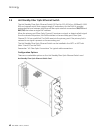
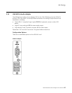
The types of communication cards included in your D400 depend on what was ordered
for your substation application.
For a list and detailed description of the types of communication cards available, see
chapter “3 Setting up Communication Cards”.
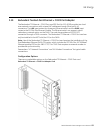
General Cabling Requirements
Cabling required to make physical connections to the D400 are as follows:
Media Designation Cabling Connector
Single Fiber Optic
Ethernet
10BaseFL
100BaseSX
62.5/125 µm or
50/125 µm multi-mode
fiber cable
ST Connectors
(820-850 nm)
Single Twisted Pair
10/100BaseT UTP– Unshielded Twisted
Pair – CAT 5 or better
RJ-45
Redundant Twisted Pair
10/100BaseT UTP– Unshielded Twisted
Pair – CAT 5 or better
RJ-45
PPP Serial Over External
Modem V.90 (56 Kbps)
RS-232 Standard RS-232 cable DB-9