


GE Energy
36
994-0089–1.00–2, General
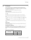
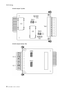
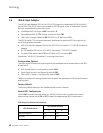
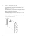
3.6 IRIG-B Input Adapter
The IRIG-B Input Adapter (GE Part No. 520-0211) plugs into a dedicated IRIG-B slot (slot 9)
on the D400. The IRIG-B Input card accepts an IRIG-B signal in one of three input formats
through a corresponding connector type:
• Modulated IRIG-B through a BNC connector J2
• Demodulated IRIG-B (TTL) through a terminal block TB1
• Fiber Optic through a Receive (RX) 820-850 nm ST connector U12
The IRIG-B signal (TTL) can be subsequently distributed to attached IEDs through one of
the following output methods:
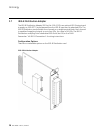
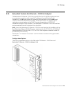
• IRIG-B Distribution Adapter (GE Part No. 520-0212). See section “3.7 IRIG-B Distribution
Adapter”
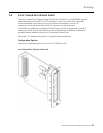
• RS-232 Adapter (GE Part No. 520-0207). See section “3.3 RS-232 Adapter”
• On-board fiber optic output (TX) on 820-850 nm ST connector U13
See section “4.6 IRIG-B Connections” for wiring instructions.
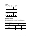
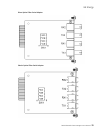
Configuration Options
The input signal formats and output options are selectable via three switches on the IRIG-
B Input card:
• IRIG-B state option is configured by switch SW1
• Input signal format is configured by switch SW2
• Fiber optic TX option is configured by switch SW3
Follow instructions for setting the switches to select the appropriate IRIG-B signal formats
and functions
.
Factory Default
The factory default setting is the Standard state on each channel.
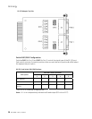
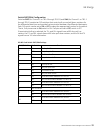
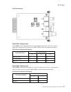
Switch SW1 Configuration
Switch SW1 controls the state option for the IRIG-B Input card. It contains two switch
positions that can be set to ON or OFF to select the appropriate IRIG-B state option.
IRIG-B Input Card Switch SW1 Settings
SW1 Switch Positions
IRIG-B State Option
1 2
Standard (default) ON OFF
Inverted OFF ON