


GFK-2251 Chapter 4 Connectors and Cabling 4-7
4
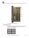
Serial Communication Ports
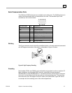
The COM1and COM2 serial ports are available on the side panel. The COM3 serial port is
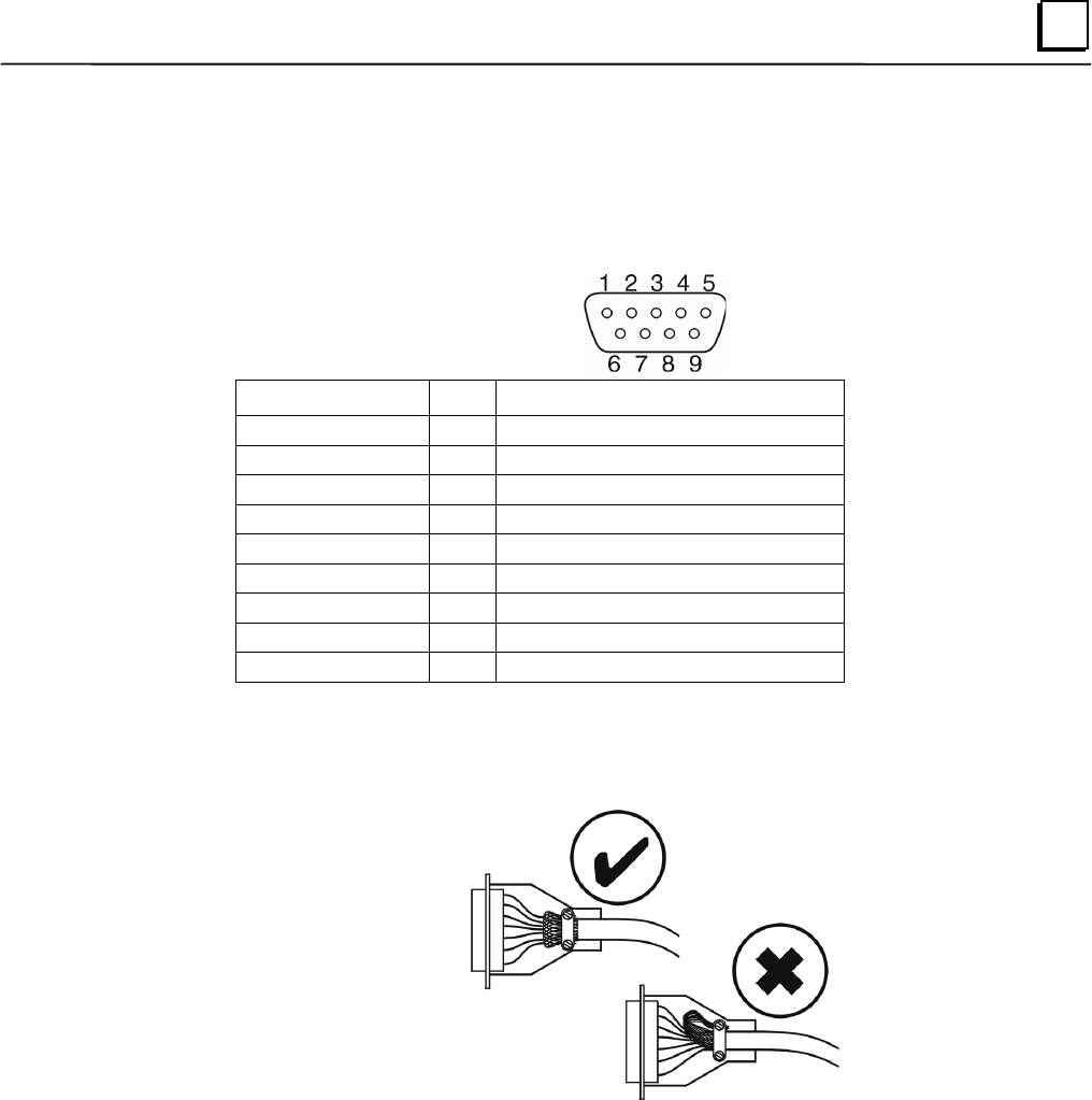
used by the touchscreen and is not accessible to the user. The standard 9-pin D-sub
connector pin out is shown below.
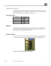
RS-232C Name Pin Assignment
CF 1 DCD (Data Carrier Detect)
BB 2 RX (Receive Data)
BA 3 TX (Transmit Data)
CD 4 DTR (Data Terminal Ready)
AB 5 GND (Signal Ground)
CC 6 DSR (Data Set Ready)
CA 7 RTS (Request to Send)
CB 8 CTS (Clear to Send)
CE 9 RI (Ring Indicator)
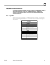
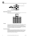
Shielding
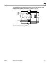
The D type connector covers should be metallized plastic or die cast metal and terminated
with 360-degree termination of the shield, as illustrated in Figure 4-3 below.
Figure 4-3. High Frequency Grounding
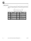
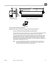
Grounding
Serial cables (COM1 and COM2) must be shielded and grounded in order to maintain CE
Mark compliance, provide higher EMC immunity, and satisfy the requirements of
IEC/EN61000-4-4 and IEC/EN61000-4-5. The shield conductor should remain continuous
to the unit, and insulation should be removed only at the grounding point. The grounding
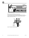
should be such that a 360-degree contact is made to the cable shield. Figure 4-4 shows
an example with the insulating cover of the cable stripped back.