


5-6 Panel C Industrial Computer Hardware User's Manual – May 2003 GFK-2251
5
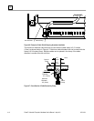
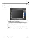
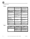
Control and Status LEDs
The Panel C industrial computer includes five status LEDs, located in a vertical column
above the arrow keys on the lower right-hand side of the unit. The five LEDs have the
following functions, in order from top to bottom:
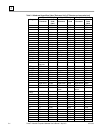
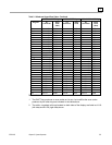
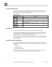
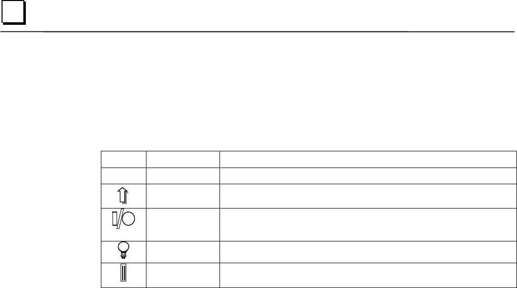
Table 5-2. Indicators
Symbol Name Function
F
FF
FN
NN
N
Function Key Indicates the function key is active.
Shift Indicates the Shift lock is enabled..
HDD/Error This is a tri-color LED. Red indicates a BIOS detected error. Green is
the normal IDE drive activity indicator. During an error the HDD/Error
LED will be Amber.
Power Indicates system power (lighted when power is applied).
Compact
Flash
Indicates Compact Flash card is inserted.
Touch Screen
The Panel C includes a resistive overlay touch screen on the flat panel display.
The touch screen has a resolution of 1024 x 1024 touch points (independent of screen
size) and provides an efficient and reliable method of entering information. The screen
responds to the touch of your finger with or without a glove.
The touch screen is connected internally to the COM3 serial port. If you install a card that
has settings that conflict with those of the COM3 serial port, you will need to change the
card’s configuration.
Touch Screen Driver for Windows
The integral touch screen of the Panel C is internally connected to COM3. Parameters
must be set within the driver so that they match the hardware settings. The factory default
settings are:
COM Port = 3
Address = 3F8 Hex
Interrupt = Com3 IRQ 9
These parameters are written into the system registry file by the driver setup utility. The
driver is installed, configured and calibrated at the time of manufacture.