


3–8 MULTILINK ML2400 ETHERNET COMMUNICATIONS SWITCH – INSTRUCTION MANUAL
INSTALLATION CHAPTER 3: INSTALLATION
3.4 Electrical Installation
3.4.1 Powering the ML2400
Units with the AC power supply option can be connected directly to 110/240 V AC with the
supplied power cord.
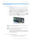
The standard high voltage (120/125 V AC/DC) or low-voltage (48 V DC) terminal block on
the ML2400 is located on the rear of the unit and is equipped with three (3) screw-down
lead posts. The power terminals are identified as positive (+), negative (–), and filter ground
( ) for DC power and as live L(+), neutral N(–), and for AC power. These terminals
are floating inside the unit so that either may be grounded by the user if desired. The
chassis or safety ground is the stud located beside the terminal block.
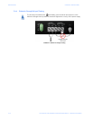
The connection procedure is straightforward. Simply insert DC leads to the ML2400 power
terminal positive (+), negative (–), and or AC leads to the live L(+), neutral N(–), and .
Please ensure the correct polarity. The should be connected to the safety ground,
except during dielectric testing. Ensure that each lead is securely tightened.
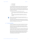
FIGURE 3–3: Power connection and alarm contacts
Note
Always use a voltmeter to measure the voltage of the incoming power supply and properly
determine the positive and negative leads.
Note
The GND should be hooked up first. The ML2400 has a floating ground, so the user may
elect to ground either the positive or negative terminal.
When power is applied, the green PWR LED will illuminate.
The ML2400 is available with a redundant power supply option. If the redundant power
supply is ordered, it should be wired as described above. The possible combinations of
redundant power supplies are: HI-HI, HI-LO, LO-HI, and LO-LO. The AC power supply cannot
be supplied with a redundant supply.
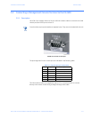
3.4.2 UL Requirements for DC-Powered Units
1. Minimum 18 AWG cable for connection to a centralized DC power source.
2. Minimum 14 AWG cable for connection to a earthing wiring.