


1
9GFK–0644A Chapter 1 Introduction
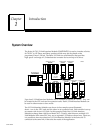
Operation of the I/O Link
The I/O Link consists of a full duplex communications channel. Physically, the link
consists of two twisted pairs of wire and a signal ground conductor. These wires are
contained in a cable that has an over–all shield. Signals are of the differential type and a
wire pair is used for each signal. Signal levels are compatible with specification EIA
RS–422/RS–485. The signal baud rate is 1.5 Mbaud maximum.
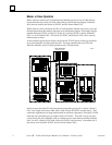
Input and Output Data
The master on an I/O Link can send 1024 outputs and receive up to 1024 inputs from
slave devices. A slave can send and receive either 32 or 64 inputs and outputs. For each
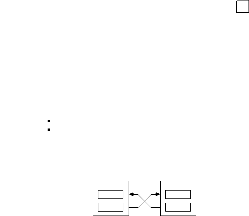
link device, inputs and outputs have the same meaning:
Input Data is data received from the link.
Output Data is data sent to the link.
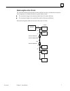
So the same set of data is considered output data by the device that sends it and input
data by the device that receives it.
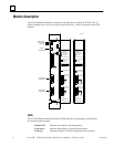
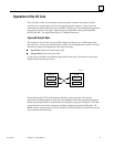
MASTER
INPUTS
a45008
OUTPUTS
SLAVE
INPUTS
OUTPUTS
For each Series 90–70 I/O Link Interface Module used as a master, %I and %Q
references and data lengths for each slave are assigned within the application Program
Block, using Logicmaster 90. Instructions for doing this are given in chapter 4. For other
types of devices on the link, references and data lengths are assigned differently. For
details on how a specific type of device handles its I/O Link data, you should refer to the
User’s Manual for that device.