


1
section level 1 1
figure bi level 1
table_big level 1
restart lowapp ARestart oddapp: ARestarts for autonumbers that do not restart in
each chapter. figure bi level 1, reset table_big level 1, reset chap_big level 1, reset1
Lowapp Alwbox restart evenap:A1app_big level 1, resetA figure_ap level 1, reset
table_ap level 1, reset figure level 1, reset Figure 1. table level 1, reset Table 1.
these restarts oddbox reset: 1evenbox reset: 1must be in the header frame of
chapter 1. a:ebx, l 1 resetA a:obx:l 1, resetA a:bigbx level 1 resetA a:ftr level 1 resetA
c:ebx, l 1 reset1 c:obx:l 1, reset1 c:bigbx level 1 reset1 c:ftr level 1 reset1
Reminders for autonumbers that need to be restarted manually (first instance will
always be 4) let_in level 1: A. B. C. letter level 1:A.B.C. num level 1: 1. 2. 3.
num_in level 1: 1. 2. 3. rom_in level 1: I. II. III. roman level 1: I. II. III. steps level 1:
1. 2. 3.
1
GFK-0644A
Chapter 1 Introduction
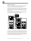
System Overview
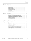
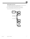
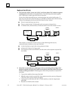
The Series 90–70 I/O Link Interface Module (IC697BEM721) is used to interface a Series
90–70 PLC to GE Fanuc and Fanuc products which may also be placed on the
proprietary Fanuc I/O Link. The Fanuc I/O Link is a serial interface that provides
high–speed exchange of I/O data between a master device and up to 16 slaves.
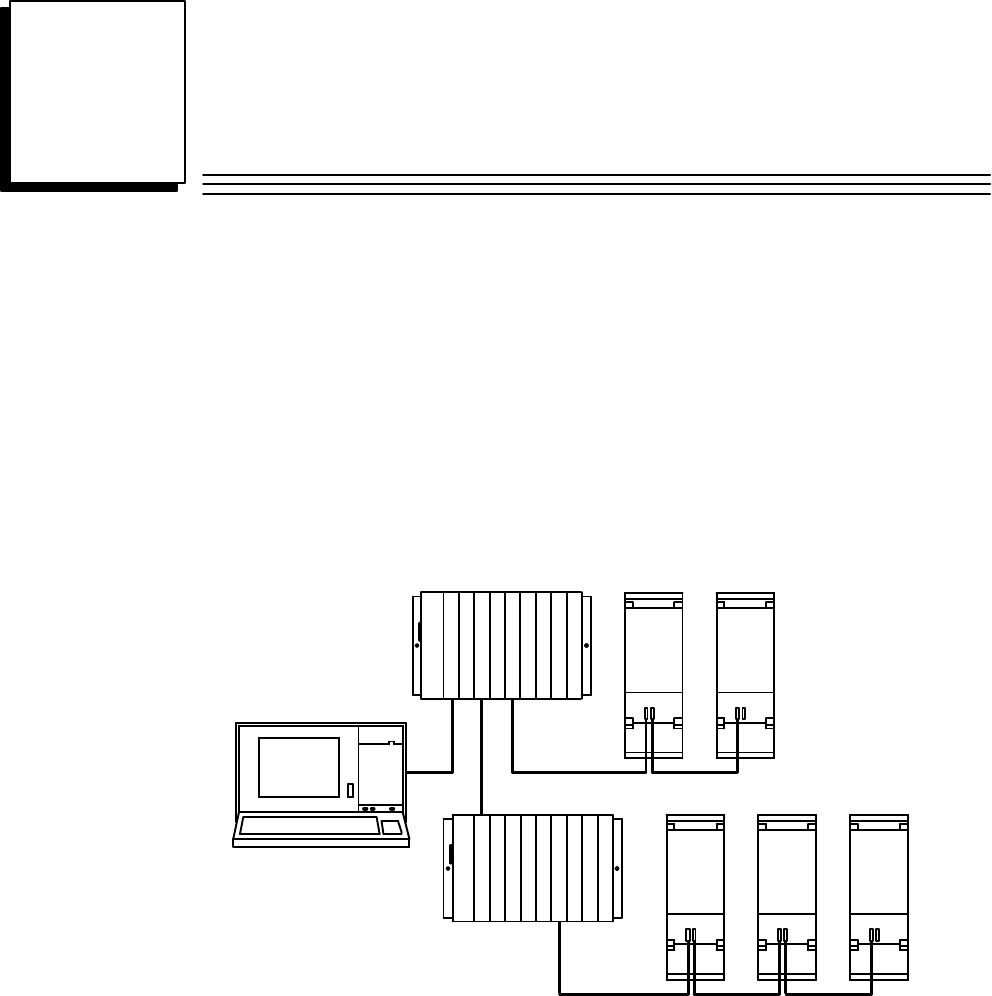
a44979SERIES 90–70 PLC
FANUC
I/O LINK
(LINK #1)
POWER MATE POWER MATE
SLAVE 0 SLAVE 1
POWER MATE POWER MATE
SLAVE 1 SLAVE 2
POWER MATE
SLAVE 0
FANUC
I/O LINK
(LINK #2)
MASTER
MASTER
WORKMASTER II
PROGRAMMER
I/O LINK
I/O LINK
PS
BRM
PS
CPU
BTM
Up to four I/O Link Interface Modules can be installed in a Series 90–70 PLC. They can
be located in the CPU rack and in expansion racks. Each I/O Link Interface Module can
be used in either master or slave mode.
Two I/O Link Interface Modules are shown in the example system illustrated
above––one in the CPU rack and the other in an expansion rack. Each module is set up
as a master with its own I/O Link. In this example, both of the I/O Link Interface
Modules exchange data with Power Mate CNCs. Usually, when there are multiple I/O
Link Modules in the same PLC, they are on separate I/O Links as shown here. However,
it is possible to have more than one I/O Link Interface Module in the Series 90–70
connected to the same link, if that suits the needs of the application.