


2
19GFK-0644A Chapter 2 Installation
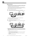
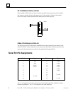
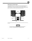
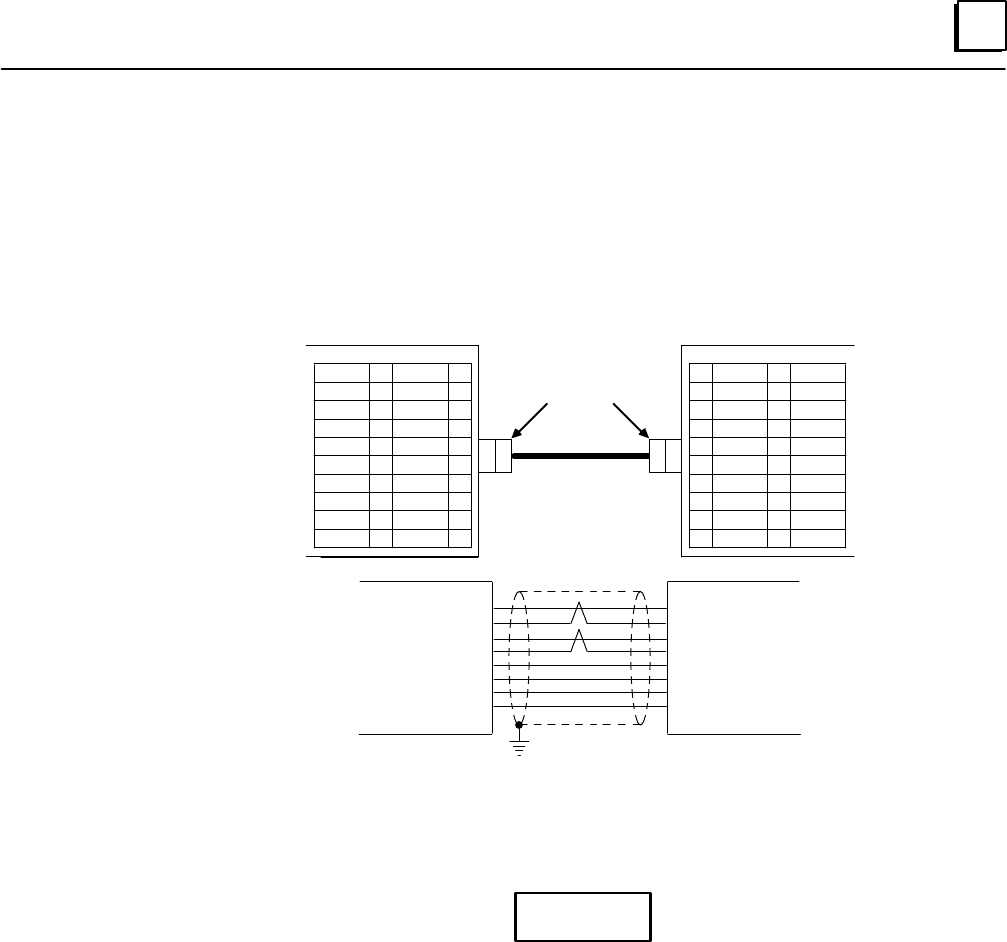
Cable Diagram, No Optical Adapter
The following illustration shows connection details for electrical cable used between a
master and slave or between two slave devices. This cable (A03B–0807–K801,
A03B–0807–K802, or cable made using AMW 2076 and connectors A02B–0120–K301)
does not include the +5–volt signal. Optical Adapter cable, which includes the +5 volt
signal, must not be used to directly connect master and slave devices.
11
12
13
14
15
16
17
18
19
20
01
02
03
04
05
06
07
08
09
10
11
12
13
14
15
16
17
18
19
20
SIN
8SIN
SOUT
*SOUT
01
02
03
04
05
06
07
08
09
10
JD1A
a45019
0V
0V
0V
0V
JD1B
SIN
SIN*
SOUT
SOUT*
PCR–E20FS
(1)
(2)
(3)
(4)
(11)
(12)
(13)
(14)
MASTER
OR
SLAVE
SIN
SIN
SOUT
SOUT
0V
0V
0V
0V
JD1A
(3)
(4)
(1)
(2)
(11)
(12)
(13)
(14)
SLAVE
SOUT
SOUT*
SIN
SIN*
0V
0V
0V
0V
JD1B
*
*
0V
0V
0V
0V
The differential signals, SIN/*SIN, and SOUT/*SOUT must be connected using twisted
pair wires.
Caution
The I/O Link cable’s shield must be connected to chassis ground in
your system. Use the grounding cable (44A729227) provided.