


2
16 Series 90 -70 I/O Link Interface Module User’s Manual – February 1993
GFK-0644A
5. A CPU module must be present in rack 0 slot 1 before applying power to the I/O Link
Interface Module. Turn on power, and observe the LEDs.
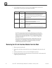
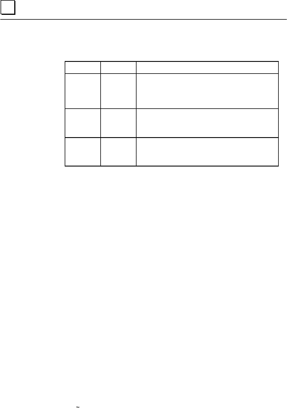
LED Name LED Status Indication
Module OK On The I/O Link Interface Module has passed its powerup
diagnostics and the hardware is operating properly.
OFF The module has failed a diagnostic test, or a run–time failure
has been detected.
Link Active On The module is communicating with the I/O Link.
OFF A failure has occurred with the I/O Link, and
communications are not possible.
Link Cfg ON I/O Link configuration has occurred, and the module is ready
to communicate.
OFF The module has not been configured for link operation.
Note
If a CPU is powered up for the first time after being received from the
factory (or for the first time after its configuration has been cleared or its
battery has been removed), and there is an I/O Link Interface Module
present in one of the racks of the PLC, a “Loss of Module” diagnostic is
generated in the PLC.
To proceed, clear the fault and download a configuration to the CPU.
See chapter 3 for configuration instructions. Once the CPU has been
configured, the “Loss of Module” diagnostic will only occur if the
module subsequently fails or is removed.
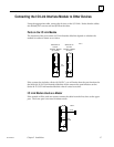
Removing the I/O Link Interface Module from the Rack
1. Remove power from the rack.
2. Squeeze the rack clips on the back of the cover to disengage the clips from the rack
rail.
3. Pull the module firmly to remove it from the backplane connector.
4. Slide the board along the card guide and remove it from the rack. Avoid contact with
neighboring boards and wiring.