


2
18 Series 90 -70 I/O Link Interface Module User’s Manual – February 1993
GFK-0644A
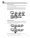
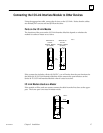
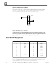
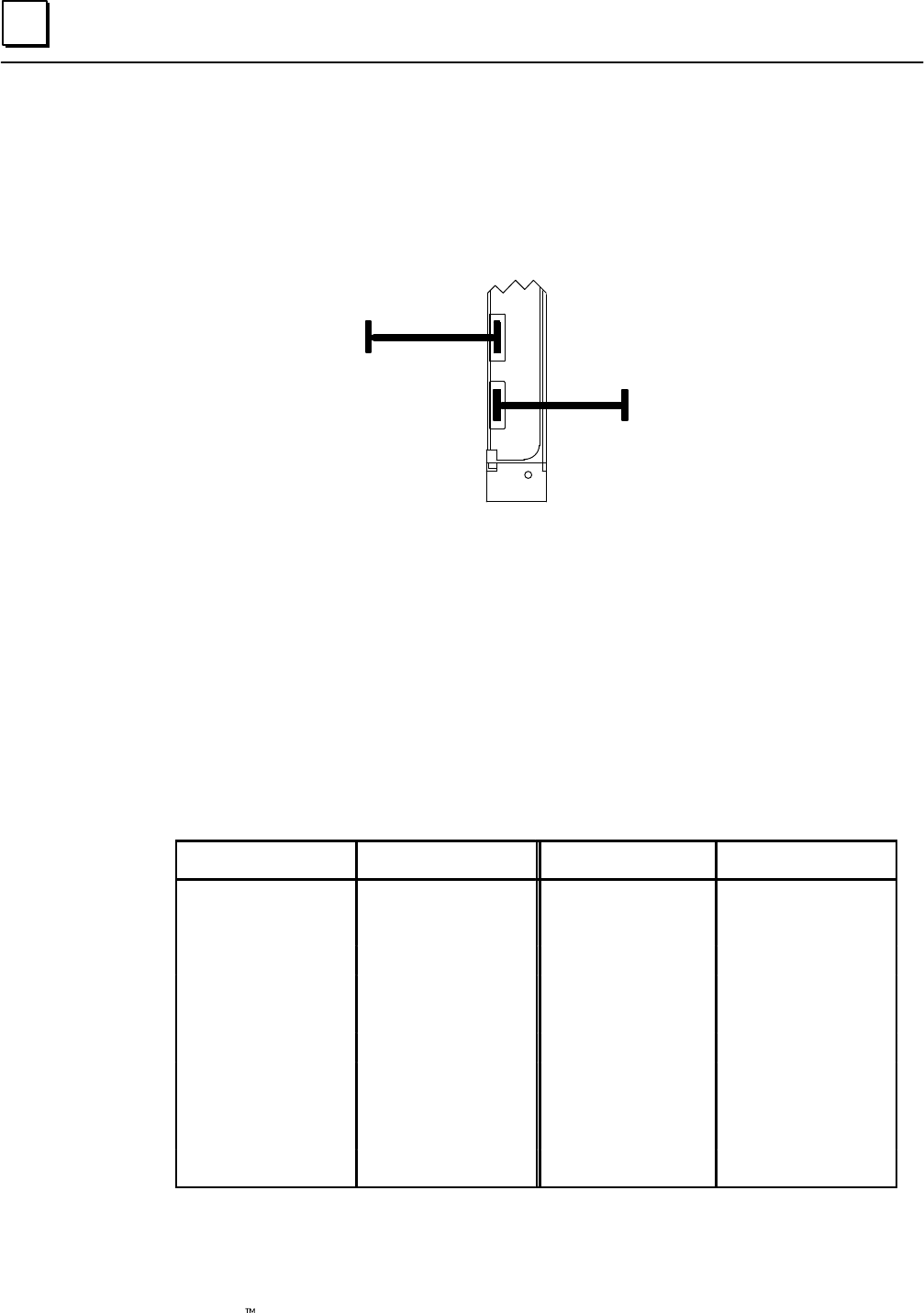
I/O Link Module Used as a Slave
If the module will be used as a slave, connect the cable from the previous device (either
the master or another slave) to the upper port. If the module is followed by another
slave on the link, connect the cable from that device to the lower port.
JD1B
JD1B
a45018
JD1A
JD1A
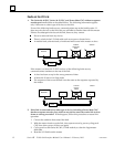
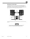
Order of the Devices on the Link
The devices on an I/O Link must be installed in the order expected by the master. If the
Series 90–70 PLC is the master, be sure to connect the devices on a link in the order that
agrees with the information provided to the application Program Block.
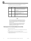
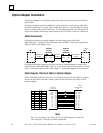
Serial Port Pin Assignments
Pin # Signal Pin # Signal
1 SIN 11 0 volts
2 *SIN 12 0 volts
3 SOUT 13 0 volts
4 *SOUT 14 0 volts
5 15 0 volts
6 16 0 volts
7 17
8 18 +5 volts
9 +5 volts 19
10 20 +5 volts
The +5–volt output from each connector powers the fiber optic link modules for long
distance applications. The +5–volt output is not used otherwise.