


4
32 Series 90 -70 I/O Link Interface Module User’s Manual – February 1993
GFK-0644A
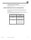
Monitoring Link Operation
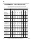
For each link, the Program Block uses a specific program register (%P) for status data.
These are:
%P00004 for link 1
%P00056 for link 2
%P00108 for link 3
%P00160 for link 4
Monitor the status word for information about:
A. the operation of the interface module
B. the operation of the link
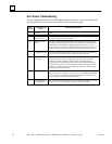
C. detailed error codes to help diagnose problems
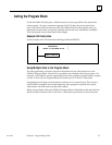
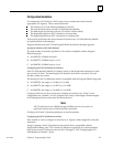
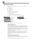
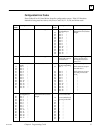
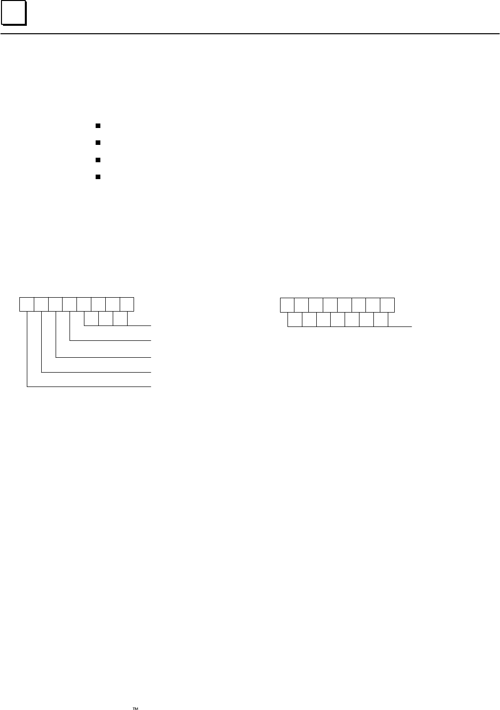
Bits in the status word for an I/O Link contain the following information:
16 15 14 13 12 11 10 9
87654321
MSB
LSB
unlabelled bits not used
reserved
Fault active = 1
Link failed = 1
Link active = 1
Board OK = 1
Error code
Bits 9 to 12 of the status word are reserved; they should be zeros.
Monitor the Module (bit 16)
This bit shows the status of module operation, and of link operation if the module is a
master. The application program should monitor this bit. If it is 0, the program should
take appropriate action such as ignoring any I/O or status information from the module.
The Program Block automatically sets bit 16 to 1 when the module passes its powerup
diagnostics, the correct rack and slot are placed in the %P configuration registers, and
VME backplane communications have been established.
The Program Block resets bit 16 to 0 if a module hardware fault is detected, or backplane
communications are interrupted.
Pressing the I/O Link Interface Module’s Reset pushbutton does not clear this bit. The
Program Block will only try to reinitialize the module after completing powerup
diagnostics. An automatic retry will occur only after link faults; the user must restart the link
after a hardware reset.
Monitor Communications Status (bit 15)
Monitor status bit 15 to check the status of communications on the link. If this bit is a 0,
input data is NOT being received, and appropriate action should be taken. The Program