


2
20 Series 90 -70 I/O Link Interface Module User’s Manual – February 1993
GFK-0644A
Optical Adapter Installation
The Optical Adapter is an optional component used to interface the electrical cable to
optical cable.
An Optical Adapter must be installed in a sealed enclosure. Avoid contact with other
electrical components or wiring, which could short the unit. Use the adapter’s casing
screws to make earth ground connection. The electrical potential of the earth ground
used for the adapter must be the same as that of the I/O Link to which it is connected.
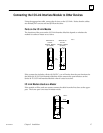
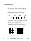
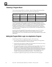
Cable Connections
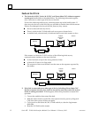
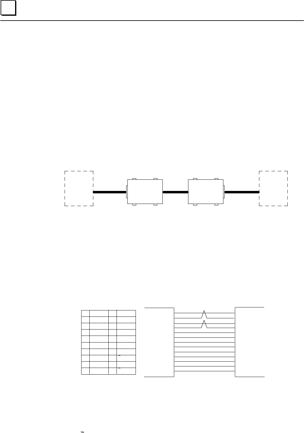
Connection between two optical adapters is made using optical fiber cable
A66L–6001–009. Lengths of 10 to 100 meters are available. Connect the optical fiber
cable to COP1 on the adapter unit.
a45014
OPTICAL
CABLE
OPTICAL
I/O LINK
ADAPTOR
OPTICAL
I/O LINK
ADAPTOR
ELECTRICAL
CABLE
JD1 COP1 COP1 JD1
UNIT
JD1B
UNIT
JD1A
ELECTRICAL
CABLE
Connection between a master or slave device and an Optical Adapter is made using
electrical cable A03B–0807–K803, which is a one–meter cable with connectors on both
ends. Connect this cable to JD1 on the adapter. A connection diagram is shown below.
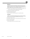
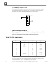
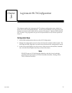
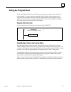
Cable Diagram, Electrical Cable to Optical Adapter
Cable A03B–0807–K803 provides the +5–volt signal required by the Optical Adapter.
Do not use this cable to directly connect master or slave devices; use it only with an
Optical Adapter.
+5V
(01)
(02)
(03)
(04)
(09)
(18)
(20)
(11)
(12)
(13)
(14)
(15)
(16)
ADAPTER SIDE
JD1
SOUT
SOUT
SIN
SIN*
+5V
+5V
+5V
0V
0V
0V
0V
0V
0V
*
UNIT SIDE
JD1A, JD1B
(03)
(04)
(01)
(02)
(09)
(18)
(20)
(11)
(12)
(13)
(14)
(15)
(16)
a45020
11
12
13
14
15
16
17
18
19
20
01
02
03
04
05
06
07
08
09
10
0V
0V
0V
0V
SIN
SIN
SOUT
SOUT
*
*
0V
0V
+5V
+5V
SIN
*SIN
SOUT
*SOUT
+%V
+5V
+5V
0V
0V
0V
0V
0V
0V
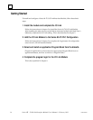
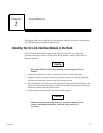
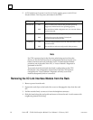
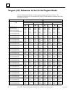
Note
The +5–volt output on the Series 90–70 I/O Link Module is fused with
a 0.5 Amp fuse. The fuse is not field replaceable.