


4
30 Series 90 -70 I/O Link Interface Module User’s Manual – February 1993
GFK-0644A
Controlling the I/O Link Module
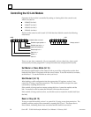
Operation of the module is controlled by setting or clearing bits in the control word,
which is located at:
%P00005 for link 1
%P00057 for link 2
%P00109 for link 3
%P00161 for link 4
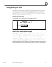
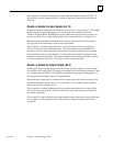
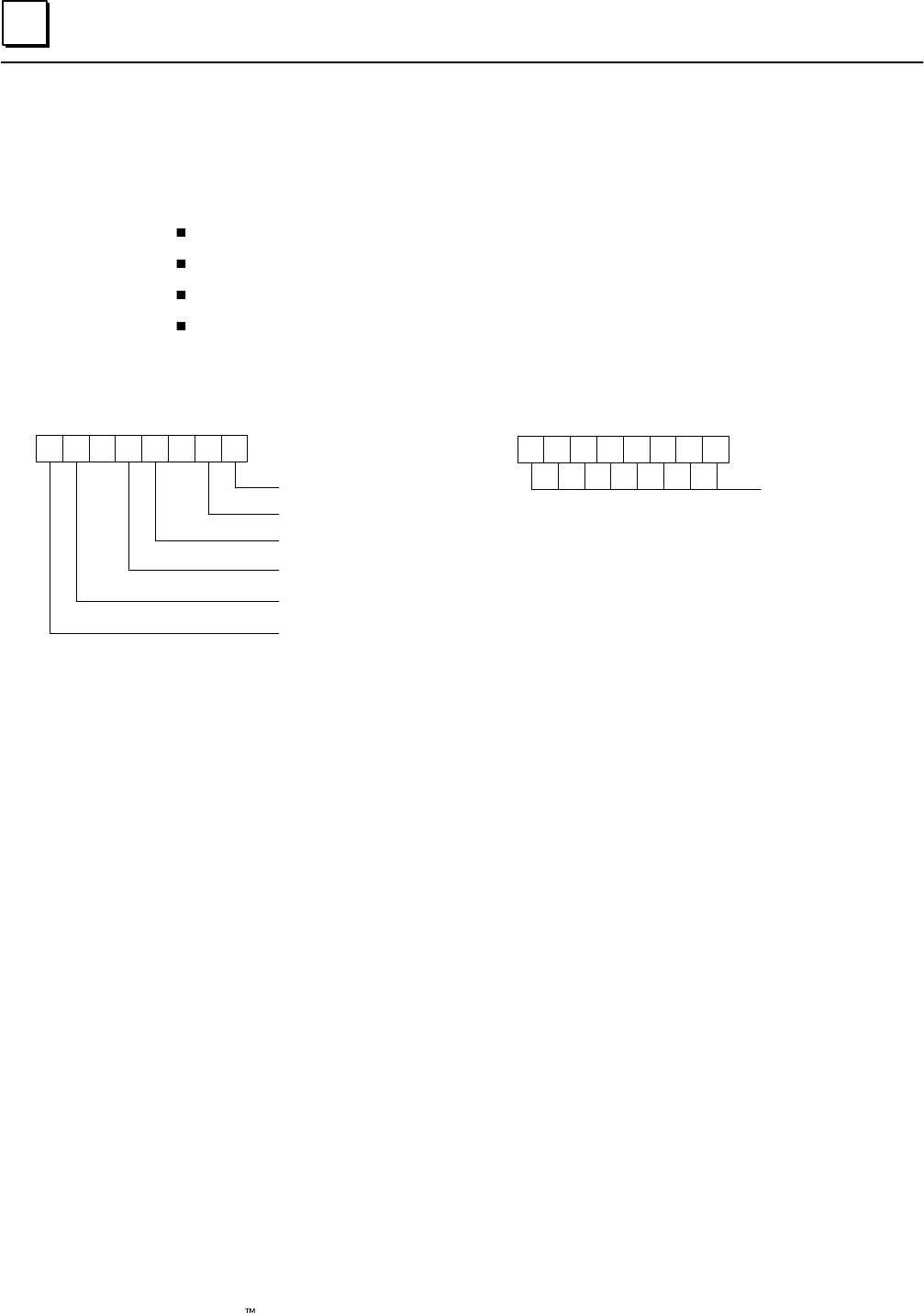
The bits in the control word for each I/O Link Interface Module contain the following
information:
16 15 14 13 12 11 10 9
87654321
MSB
LSB
unlabelled bits not used
Disable output update = 1
Disable input scan = 1
reserved (must be 0)
Reset/stop link = 1
Start link = 1
Master = 1
Slave=0
Always set to 0
These are one–shot commands. Do not repeatedly write to these bits––that would
unnecessarily increase program PLC sweep time and cause unexpected link results.
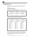
Set Master or Slave Mode (bit 16)
Set the most significant bit of the control word as part of the configuration routine that
loads all of the other %P registers with the correct values. To use the module as a master,
set this bit to 1. To use the module as a slave, set it to 0.
Start/Restart (bit 15)
After loading a valid configuration into the appropriate %P registers, write a 1 into
control bit 15 using a one–shot permissive. The module confirms receipt of the start
command by resetting this bit to a 0.
If the module is being used as a master, setting this bit to 1 starts the module and the
link. It can also be used to restart the link after a link reset has occurred.
If the module is being used as a slave, use this bit to start or restart the module itself (not
the link).
Reset or Stop (bit 13)
To stop or reset the module, write a 1 to control bit 13, using a one–shot permissive. The
module confirms receipt of the command by resetting bit 13 to a 0. The status shows
Error Code 6, indicating that a reset was issued and the fault bit was not set.