


1
2 Series 90 -70 I/O Link Interface Module User’s Manual – February 1993
GFK-0644A
Master or Slave Operation
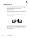
When used as a master, an I/O Link Interface Module can receive up to 1024 discrete
inputs from devices on the I/O Link, and send up to 1024 discrete outputs. Potential
slave devices include the Series 90–30 PLC and the Power Mate CNC.
When used as a slave, the Series 90–70 I/O Link Interface Module can receive up to 64
discrete inputs from the master, and send up to 64 discrete outputs. The master may be
another Series 90–70 PLC, a Series 15, Series 16, or Series 18 CNC, a Series 0 Model C
CNC, or an F–D Mate CNC. The Series 90–70 PLC and Series 0 CNC can be used as
either master or slave.
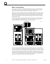
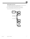
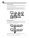
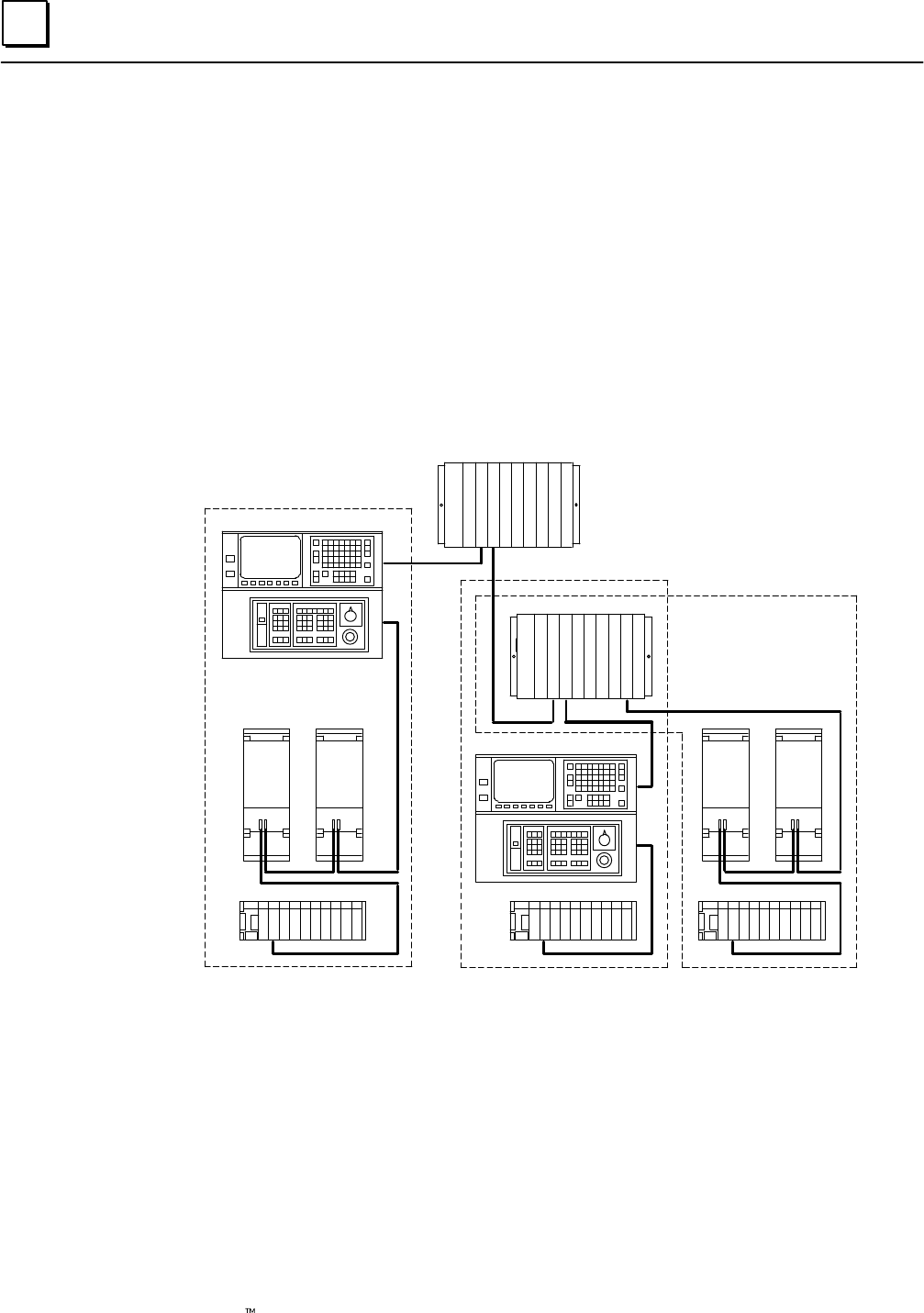
In the example system shown below, the Series 90–70 PLC shown at the top functions
as an area controller for three machine cells. The area controller has two I/O Link
Interface Modules, each of which operates as an I/O Link master.
I/O LINK
POWER MATE POWER MATE
a45002
SERIES 90–70 PLC
AREA CONTROLLER
CELL #3
I/O LINK
SERIES 0 CNC
I/O LINK
CELL #1
SERIES 0 CNC
CELL #2
I/O LINK
SERIES 90–70 PLC
SERIES 90–30 PLCSERIES 90–30 PLCSERIES 90–30 PLC
POWER MATE POWER MATE
I/O LINK
I/O LINK
I/O LINK
I/O LINK
I/O LINK
In this system, the left I/O Link from the area controller goes to cell 1, where a Series 0
CNC, two single–axis Power Mate CNCs, and a Series 90–30 PLC are the slaves. They
control the operations of a large machine and its auxiliary equipment. The right I/O Link
from the area controller goes to another Series 90–70 PLC. That PLC serves as a slave
on the link to the area controller, and as a master on two other links to smaller machine
cells. In cell 2, a Series 0 CNC and a Series 90–30 PLC are the slaves. In machine cell 3,
the slaves are a Series 90–30 PLC and two Power Mate CNCs.