


1
12 Series 90 -70 I/O Link Interface Module User’s Manual – February 1993
GFK-0644A
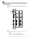
Faults on the I/O Link
A. The Series 90–30 PLC, Series 90–70 PLC, and Power Mate CNC without a separate
encoder port handle faults as described below. The following information applies
only if there are no other types of devices on the link.
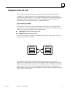
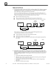
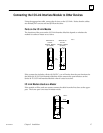
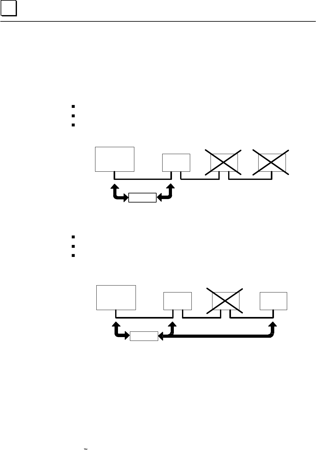
If one of the following faults occurs, communications stop at the fault location. If
there are prior devices on the link, they are still able to transfer data with the master.
If there are subsequent devices on the link, however, they cannot.
Power is removed from any device.
There is a fault in the I/O Link cable such as an open or shorted wire.
A module fault, software fault, or hardware fault occurs in the master or slave.
MASTER
DATA
SLAVE
2
SLAVE
3
POWER
REMOVED
HERE
a45010
SLAVE
1
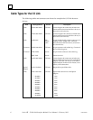
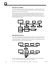
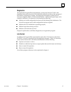
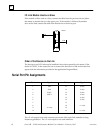
If the master is a Series 90–70 PLC and one of the following faults occurs,
communications continue on the rest of the link.
A slave has been set up for the wrong amount of data.
A Series 90–30 slave is in Stop mode.
The sequence of slaves on the link is not the same as the sequence expected by
the master.
MASTER
DATA
SLAVE
1
SLAVE
2
SLAVE
3
PLACED
IN STOP
MODE
a45011
B. If the link is connected to any other type of device, including a Power Mate CNC
that has a separate encoder port, a fault on any device causes the entire link to shut
down as a safety precaution. If that happens, follow this procedure to restore link
operation.
1. Correct the condition that caused the fault.
2. With the master inactive on the link, clear system errors by power cycling each
CNC slave (turn power off, then on again).
3. Cycle power to each Series 90–30 I/O Link module, to clear the Logicmaster
fault table.
4. Reset the I/O link from the master.