4
section level 1 1
figure bi level 1
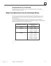
table_big level 1
23
GFK-0644A
Chapter 4 Programming Guide
This chapter explains how to incorporate logic for one to four I/O Link Interface
Modules in an application program for the Series 90–70 PLC. Programming instructions
for other devices on the link are not included.
Overview
The Program Blocks on the diskettes provided with the I/O Link Interface Module will
transfer input and output data between the Series 90–70 PLC and up to four I/O Link
Interface Modules. The Program Blocks also monitor diagnostics from each I/O Link
Interface Module in the PLC, and provide a mechanism for controlling link operation
from the application program.
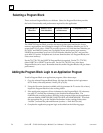
One Program Block is selected for the application, and added to the application program
using the Librarian function of Logicmaster 90–70.
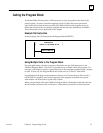
Logic must be added to the application program to call the Program Block, which will
execute once each time it is called. Normally, it is called once per PLC sweep.
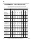
The Program Block utilizes a range of %P references, set aside in PLC memory, to
exchange data with the Series 90–70 PLC. The application program interfaces with the
Program Block by reading and writing the same %P references. The Program Block also
makes use of a small group of %G references. These do not require any application
program interaction. However, it is important to be sure that these %G references are
not used for any other purpose.


