


4
29GFK–0644 Chapter 4 Programming Guide
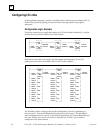
Configuration Guidelines
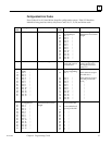
To configure the I/O Link(s) in a PLC system, enter constant data values into the
appropriate %P registers. These values determine:
The number of I/O Link Interface Modules in the PLC.
The rack and slot location of each I/O Link Interface Module.
The data length for each slave device (32 or 64 for a Power Mate).
The beginning address in PLC %I memory for input data.
The beginning address in PLC %Q memory for output data.
This must be done before the start command is issued to any I/O Link Interface Module
(as explained later in this chapter).
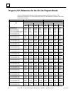
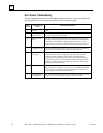
Program references for the I/O Link Program Blocks are listed in the table opposite.
Specify the Number of I/O Link Modules
The total number of modules specified in %P must be compatible with the Program
Block being used:
A. for LINK73X, %P00001 must be 1
B. for LINK77X, %P00001 may be 1 or 2
C. for LINK78X, %P00001 may be 1 to 4
Configuring the I/O Link Module as a Master
If the I/O Link Interface Module is a master, specify a data length and references for each
slave on the I/O Link. The data length (I/O count) for each device must be 0, 32, or 64.
No other values are correct.
The starting %I and %Q addresses must be compatible with the Program Block being used:
A. for LINK73X, the range is (1 to 481) or (1 to 449)
B. for LINK77X, the range is (1 to 2017) or (1 to 1985)
C. for LINK78X, the range is (1 to 4065) or (1 to 4033)
Configure all devices to have consecutive numbers; do not leave any “holes” in the
configuration for a module. If a 0 is configured for a slave’s data length, the data lengths
of all subsequent slaves on the same link must also be 0.
Note
All %P references from %P0009 through %P0209 which are not used for the
application must be set to 0 before the link is activated.
Configure all %I and %Q starting addresses at word boundaries.
Configuring the I/O Link Module as a Slave
If the module is a slave, configure it to be Device 0. Specify its data length (32 or 64) and
references.
Assign a starting %I and %Q address for the module that is compatible with the
Program Block being used. The %I and %Q addresses must begin on word boundaries.
Set to 0 the unused %P references for devices 1 through 15. See “Configuring the I/O
Link Module as a Master”, above.