5
PANEL DESCRIPTIONS
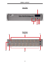
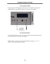
1 Main LCD Display
This 2 line 16 character display will display status information and is also used to
manage the display/source routes.
2 Control Buttons
These buttons are used to navigate the functions of the 16x16 DVI Matrix. For
complete details on these controls and how they are used, please see page 7
and 8.
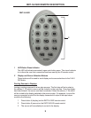
3 Infrared (IR) Receiver
This IR receiver will accept commands from the RMT-16416IR remote control.
Line-of-sight between this receiver and the remote controls needs to be
preserved for proper operation.
4 Power LED Indicator
This LED indicator will be active when the included 24V DC power supply is
properly connected to the unit.
5 Cancel Button
This button is used to return the user to the main status screen once a routing
change has been initiated and the user decides to not continue with the change.
6 RS-232 Serial Communications Interface
This interface was designed to accept commands from an external control
system. This port will allow switching commands as well as EDID management
and confi guration operations. Please see page 14 for more information.
7 DVI Output Ports 1-16
These outputs are used to connect up to 16 DVI-capable displays.
8 24V DC Power Receptacle
The port will accept power from the included 24V DC power supply.
9 10/100 Ethernet Control Interface
This port is used to connect the 16x16 DVI Matrix to a network for IP control.
Please see page 29 for more information.
10 DVI Input Ports 1-16
These inputs are used to connect up to 16 DVI-capable sources.
11 DIP Switch Confi guration Bank
These DIP switches are not used and are for future use.
12 IR Extender Jack
Accepts an optional IR Extender which allows relocation of the IR receiver up to
6 feet away from the Matrix.


