


Multiple Instance Spanning-Tree Operation
Overview
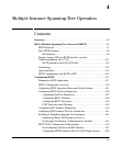
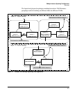
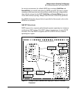
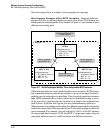
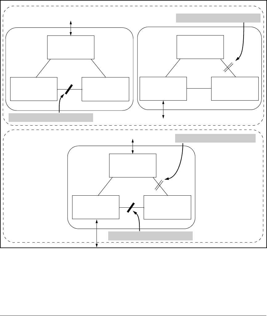
The logical and physical topologies resulting from these VLAN/Instance
groupings result in blocking on different links for different VLANs:
Switch “C”
Instance 1
VLANs: 10, 11, 12
Switch “A”
Root for Instance 1
VLANs: 10, 11, 12
Switch “B”
Instance 1
VLANs: 10, 11, 12
Switch “C”
Instance 2
VLANs: 20, 21, 22
Switch “A”
Instance 2
VLANs: 20, 21, 22
Switch “B”
Root for Instance 2
VLANs: 20, 21, 22
Switch “C”
Switch “A”
Root for Instance 1
Switch “B”
Root for Instance 2
Path blocked for VLANs in instance 1.
Path blocked for VLANs in instance 2.
Region “A”: Logical Topology
Path blocked for VLANs in instance 1.
Path blocked for VLANs in instance 2. Region “A”: Physical Topology
Figure 4-1. Example of a Multiple Spanning-Tree Application
4-5