


QinQ (Provider Bridging)
Introduction
Introduction
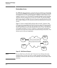
The IEEE 802.1ad specification, commonly known as QinQ or provider bridg-
ing, extends the IEEE 802.1Q standard by providing for a second tier of VLANs
in a bridged network. The general purpose of QinQ is to allow frames from
multiple customers to be forwarded (or tunneled) through another topology
(provider network) using service VLANs or S-VLANs. The provider bridge,
which may comprise multiple devices in the service provider domain, looks
like a simple bridge port to the customers traffic and maintains the customer’s
VLANs.
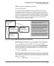
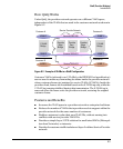
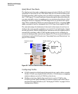
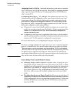
Figure 8-1 shows a sample QinQ topology and use model. Customer A has
LANs spread across multiple site locations and may want to link them together
in a single logical LAN. To do this, the customer could have a cable laid out
for the entire distance interconnecting the three sites. A more cost-effective
and scalable alternative, however, would be to tunnel frames through the
provider’s network to interconnect all the sites subscribing to the service. This
solution can be delivered using QinQ.
Service Provider Network
Customer A
Site 1
Customer A
Site 2
Customer B
Site 1
Customer A
Site 3
Customer B
Site 2
(Interconnects geographically
disparate LANs of each customer)
Figure 8-1. QinQ Network Diagram
Note The so-called ‘Service Provider’ and ‘Customers’ may belong to the same
business entity, as in the case where a single enterprise uses QinQ to help
segregate local networks and increase the scalability of their backbone infra-
structure.
8-4