


QinQ (Provider Bridging)
Configuration Example
Configuration Example
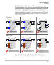
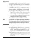
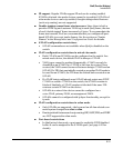
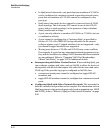
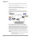
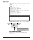
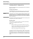
Figure 8-6 shows a configuration example that uses four ProCurve switches
to establish a QinQ tunnel through the provider network.
1 – 10
1 – 20
Customer
VLANs
A1
A2
1 – 10
1 – 20
A1
A1
A1
A2
A2
A2
A3
A3
A3
A3
A4
A4
Provider
Edge 1
Provider
Edge 2
Provider
Core 1
Provider
Core 2
Customer B
Site 1
Customer B
Site 2
Customer A
Site 1
Customer A
Site 2
100
200
Customer-network “ports (A1 and A2) accept all
tagged and untagged frames and put them into a
single S-VLAN per customer.
100 ( 1 – 10 );
S-VLANs
200 ( 1 – 20 );
100 ( 1 – 10 );
200 ( 1 – 20 );
Service Provider Network
100 ( 1 – 10 );
200 ( 1 – 20 );
100 ( 1 – 10 );
200 ( 1 – 20 );
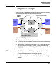
Figure 8-6. QinQ Configuration Example
The design parameters for this example are as follows:
■ The provider edge bridge and the provider core bridge are configured in
svlan mode.
■ Each customer is associated with a single S-VLAN connecting two sepa-
rate sites: customer A’s VLANs (C-VLANs 1-10) are associated with
S-VLAN 100; and customer B’s VLANs (C-VLANs 1-20) are associated with
S-VLAN 200.
Notes ■ The VLANs of customers A and B can overlap: this will not result in
intermixing of customer frames in the provider cloud because the
S-VLANs associated with each customer are different.
■ Core devices are not mandatory to establish a QinQ tunnel. For example,
two edge-bridges can be connected directly to create a provider bridge
network.
8-17