


Technical Reference Guide 361834-002 5-15
Input/Output Interfaces
5.5.3 Extended Capabilities Port Mode
The Extended Capabilities Port (ECP) mode, like EPP, also uses a hardware protocol-based
design that supports transfers up to 2 MB/s. Automatic generation of addresses and strobes as
well as Run Length Encoding (RLE) decompression is supported by ECP mode. The ECP mode
includes a bi-directional FIFO buffer that can be accessed by the CPU using DMA or
programmed I/O. For the parallel interface to be initialized for ECP mode, a negotiation phase is
entered to detect whether or not the connected peripheral is compatible with ECP mode. If
compatible, then ECP mode can be used.
Ten control registers are available in ECP mode to handle transfer operations. In accessing the
control registers, the base address is determined by address lines A2-A9, with lines A0, A1, and
A10 defining the offset address of the control register. Registers used for FIFO operations are
accessed at their base address + 400h (i.e., if configured for LPT1, then 378h + 400h = 778h).
The ECP mode includes several sub-modes as determined by the Extended Control register. Two
submodes of ECP allow the parallel port to be controlled by software. In these modes, the FIFO
is cleared and not used, and DMA and RLE are inhibited.
5.5.4 Parallel Interface Programming
Programming the parallel interface consists of configuration, which typically occurs during
POST, and control, which occurs during runtime.
Parallel Interface Configuration
The parallel interface must be configured for a specific address range (LPT1, LPT2, etc.) and
also must be enabled before it can be used. When configured for EPP or ECP mode, additional
considerations must be taken into account. Address selection, enabling, and EPP/ECP mode
parameters of the parallel interface are affected through the PnP configuration registers of the
LPC47B397 I/O controller. Address selection and enabling are automatically done by the BIOS
during POST but can also be accomplished with the Setup utility and other software.
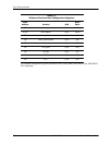
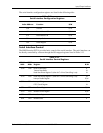
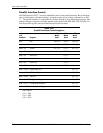
The parallel interface configuration registers are listed in the following table:
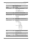
Table 5-13.
Parallel Interface Configuration Registers
Index
Address Function R/W Reset Value
30h Activate R/W 00h
60h Base Address MSB R/W 00h
61h Base Address LSB R/W 00h
70h Interrupt Select R/W 00h
74h DMA Channel Select R/W 04h
F0h Mode Register R/W 00h
F1h Mode Register 2 R/W 00h