


5-28 361834-002 Technical Reference Guide
Input/Output Interfaces
USB Control
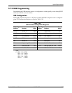
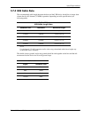
The USB is controlled through I/O registers as listed in table 5-21.
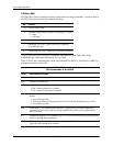
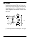
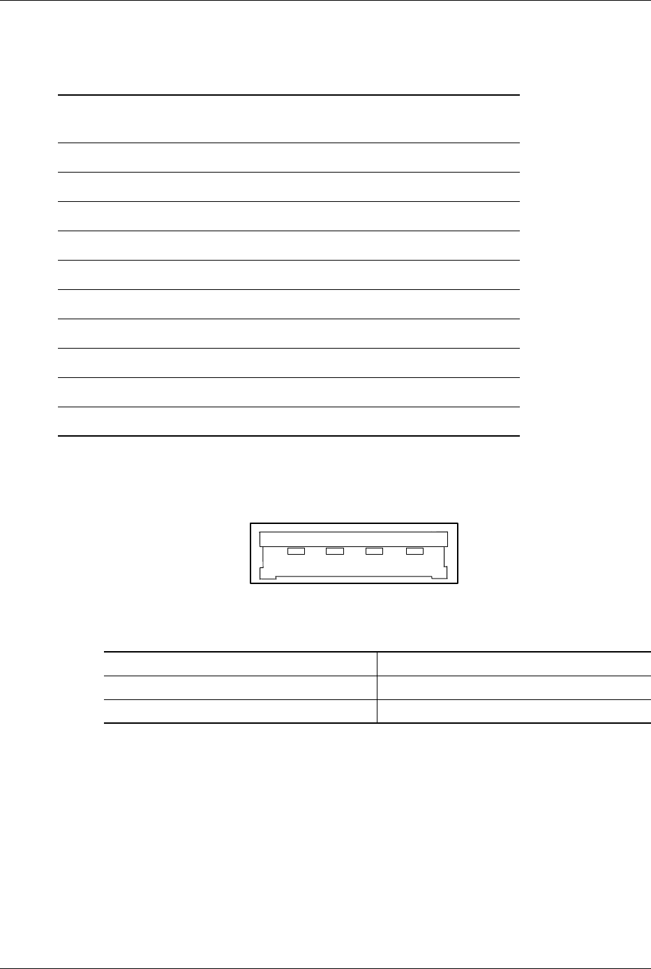
5.7.3 USB Connector
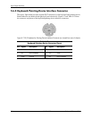
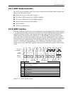
These systems provide type-A USB ports as shown in Figure 5-10 below.
Figure 5-10. Universal Serial Bus Connector (Female)
Table 5-21.
USB Control Registers
I/O Address Register Default Value
00, 01h Command 0000h
02, 03h Status 0000h
04, 05h Interupt Enable 0000h
06, 07 Frame Number 0000h
08, 0B Frame List Base Address 0000h
0Ch Start of Frame Modify 40h
10, 11h Port 1 Status/Control 0080h
12, 13h Port 2 Status/Control 0080h
18h Test Data 00h
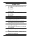
Table 5-22.
USB Connector Pinout
Pin Signal Description Pin Signal Description
1 Vcc +5 VDC 3 USB+ Data (plus)
2 USB- Data (minus) 4 GND Ground
1 2
3 4