


5-6 361834-002 Technical Reference Guide
Input/Output Interfaces
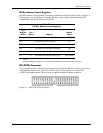
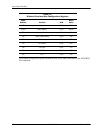
SATA Bus Master Control Registers
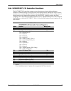
The SATA interface can perform PCI bus master operations using the registers listed in Table
5-5. These registers occupy 16 bytes of variable I/O space set by software and indicated by PCI
configuration register 20h in the previous table. As indicated, these registers are virtually a copy
of those used by EIDE operations discussed in the EIDE section.
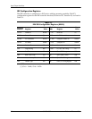
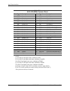
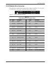
SATA Connector
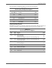
The 7-pin SATA connector is shown in the figure below.
Figure 5-2. 7-Pin SATA Connector (on system board).
Table 5-5.
IDE Bus Master Control Registers
I/O Addr.
Offset
Size
(Bytes) Register Default Value
00h 1 Bus Master IDE Command (Primary) 00h
02h 1 Bus Master IDE Status (Primary) 00h
04h 4 Bus Master IDE Descriptor Pointer (Primary) 0000 0000h
08h 1 Bus Master IDE Command (Secondary) 00h
0Ah 2 Bus Master IDE Status (Secondary) 00h
0Ch 4 Bus Master IDE Descriptor Pointer (Secondary 0000 0000h
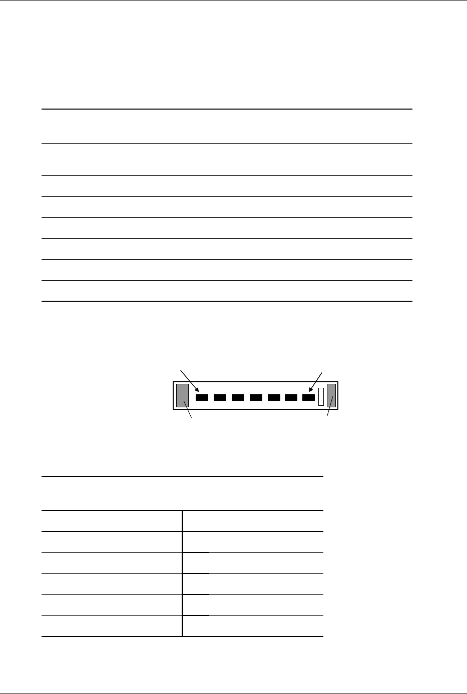
Table 5-6.
7-Pin SATA Connector Pinout
Pin Description Pin Description
1Ground 6RX positive
2TX positive 7Ground
3 TX negative A Holding clip
4 Ground B Holding clip
5 RX negative -- --
Pin 1
Pin 7
A
B