


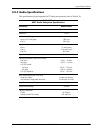

Technical Reference Guide 361834-002 5-31
Input/Output Interfaces
5.8.1 AC97 Audio Controller
The AC97 Audio Controller is a PCI device that is integrated into the 82801 ICH component and
supports the following functions:
■ Read/write access to audio codec registers
■ 16-bit stereo PCM output @ up to 48 KHz sampling
■ 16-bit stereo PCM input @ up to 48 KHz sampling
■ Acoustic echo correction for microphone
■ AC'97 Link Bus
■ ACPI power management
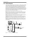
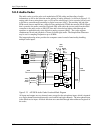
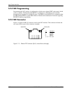
5.8.2 AC97 Link Bus
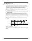
The audio controller and the audio codec communicate over a five-signal AC97 Link Bus (Figure
5-12). The AC97 Link Bus includes two serial data lines (SD OUT/SD IN) that transfer control
and PCM audio data serially to and from the audio codec using a time-division multiplexed
(TDM) protocol. The data lines are qualified by a 12.288 MHz BIT_CLK signal driven by the
audio codec. Data is transferred in frames synchronized by the 48-KHz SYNC signal, which is
derived from the clock signal and driven by the audio controller. The SYNC signal is high during
the frame's tag phase then falls during T17 and remains low during the data phase. A frame
consists of one 16-bit tag slot followed by twelve 20-bit data slots. When asserted (typically
during a power cycle), the RESET- signal (not shown) will reset all audio registers to their default
values.
Figure 5-12. AC97 Link Bus Protocol
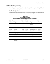
Slot Description
0 Bit 15: Frame valid bit
Bits 14-3: Slots 1-12 valid bits
Bits 2-0: Codec ID
1 Command address: Bit 19, R/W; Bits 18..12, reg. Index; Bits 11..0, reserved.
2 Command data
3 Bits 19-4: PCM audio data, left channel (SD OUT, playback; SD IN, record)
Bits 3-0 all zeros
4 Bits 19-4: PCM audio data, right channel (SD OUT, playback; SD IN, record)
Bits 3-0 all zeros
5 Modem codec data (not used in this system)
6-11 Reserved
12 I/O control
Bit 0 Bit 0 Bit 0
T1 T2
BIT_CLK
(12.288 MHz)
Codec
Ready
Bit 19 Bit 18 Bit 19 Bit 18 Bit 19
SYNC
(48 KHz)
SD OUT
or SD IN
T18 T19 T38 T39 T58
Slot 0 (Tag)
Slot 1 (Data)
Slot 2 (Data)
Bit 15 Bit 14