


Technical Reference Guide 361834-002 5-9
Input/Output Interfaces
Diskette Drive Interface Control
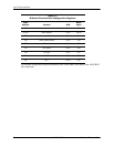
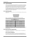
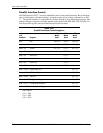
The BIOS function INT 13 provides basic control of the diskette drive interface. The diskette
drive interface can be controlled by software through the LPC47B397's I/O-mapped registers
listed in Table 5-8. The diskette drive controller of the LPC47B397 operates in the PC/AT mode
in these systems.
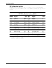
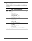
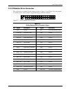
Table 5-8.
Diskette Drive Interface Control Registers
Primary
Address
Second.
Address Register R/W
3F0h 370h Status Register A:
<7> Interrupt pending
<6> Reserved (always 1)
<5> STEP pin status (active high)
<4> TRK 0 status (active high)
<3> HDSEL status (0 = side 0, 1 = side 1)
<2> INDEX status (active high)
<1> WR PRTK status (0 = disk is write protected)
<0> Direction (0 = outward, 1 = inward)
R
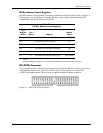
3F1h 371h Status Register B:
<7,6> Reserved (always 1’s)
<5> DOR bit 0 status
<4> Write data toggle
<3> Read data toggle
<2> WGATE status (active high)
<1,0> MTR 2, 1 ON- status (active high)
R
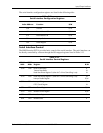
3F2h 372h Digital Output Register (DOR):
<7,6> Reserved
<5,4> Motor 1, 0 enable (active high)
<3> DMA enable (active high)
<2> Reset (active low)
<1,0> Drive select (00 = Drive 1, 01 = Drive 2, 10 = Reserved, 11 =
Tape drive)
R/W
3F3h 373h Tape Drive Register (available for compatibility) R/W