


Technical Reference Guide 361834-002 5-17
Input/Output Interfaces
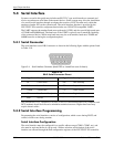
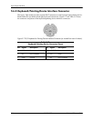
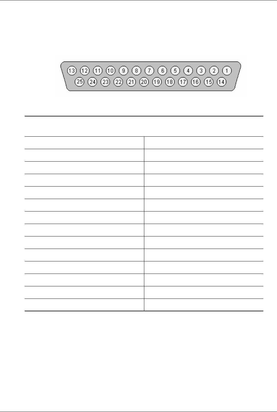
5.5.5 Parallel Interface Connector
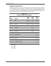
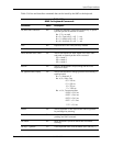
Figure 5-5 and Table 5-15 show the connector and pinout of the parallel interface connector.
Note that some signals are redefined depending on the port's operational mode.
Figure 5-5. Parallel Interface Connector (Female DB-25 as viewed from rear of chassis)
NOTES:
[1] Standard and ECP mode function / EPP mode function
[2] EPP mode function: Data Strobe
ECP modes: Auto Feed or Host Acknowledge
[3] EPP mode: user defined
ECP modes:Fault or Peripheral Req.
[4] EPP mode: Reset
ECP modes: Initialize or Reverse Req.
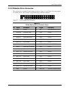
Table 5-15.
DB-25 Parallel Connector Pinout
Pin Signal Function Pin Signal Function
1 STB- Strobe / Write [1] 14 LF- Line Feed [2]
2D0 Data 0 15ERR- Error [3]
3 D1 Data 1 16 INIT- Initialize Paper [4]
4 D2 Data 2 17 SLCTIN- Select In / Address. Strobe [1]
5D3 Data 3 18GNDGround
6D4 Data 4 19GNDGround
7D5 Data 5 20GNDGround
8D6 Data 6 21GNDGround
9D7 Data 7 22GNDGround
10 ACK- Acknowledge / Interrupt [1] 23 GND Ground
11 BSY Busy / Wait [1] 24 GND Ground
12 PE Paper End / User defined [1] 25 GND Ground
13 SLCT Select / User defined [1] -- -- --