


Technical Reference Guide 361834-002 7-13
Power and Signal Distribution
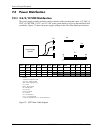
7.4 Signal Distribution
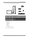
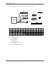
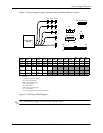
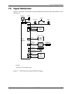
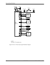
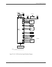
Figures 7-7 through 7-9 show general signal distribution between the main subassemblies of the
system units.
NOTES:
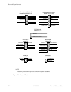
See Figure 7-10 for header pinout.
Figure 7-7. USDT Form Factor Signal Distribution Diagram
P8
+12 VccP
Power LED
IDE I/F.,
P1
Power
P6
P5
P3
Supply
Assembly
+3.3, +5, +12 VDC
MultiBay
Front
Mouse
PS On, POK
Hard Drive
SATA
Keyboard
P60
P21
P23
Daughter
Board
Diskette I/F.,
CD Audio
HD LED
System
Chassis Fan
Speaker
CD, DVD, or
P24
Panel
I/O Module
Board
356023-001
Power On
J66
IDE I/F
USB 6,7 Tx/Rx
Kybd data
Mic In, HP Out
Audio
Mouse data
Diskette Drive
J67