


Technical Reference Guide 361834-002 4-17
System Support
DMA Page Registers
The DMA page register contains the eight most significant bits of the 24-bit address and works in
conjunction with the DMA controllers to define the complete (24-bit) address for the DMA
channels. Table 4-10 lists the page register port addresses.
NOTE:
The DMA memory page register for the refresh channel
must be programmed with 00h for proper operation.
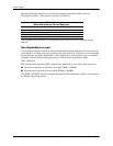
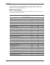
The memory address is derived as follows:
Note that address line A16 from the DMA memory page register is disabled when DMA
controller 2 is selected. Address line A00 is not connected to DMA controller 2 and is always 0
when word-length transfers are selected.
By not connecting A00, the following applies:
■ The size of the the block of data that can be moved or addressed is measured in 16-bits
(words) rather than 8-bits (bytes).
■ The words must always be addressed on an even boundary.
DMA controller 1 can move up to 64 Kbytes of data per DMA transfer. DMA controller 2 can
move up to 64 Kwords (128 Kbytes) of data per DMA transfer. Word DMA operations are only
possible between 16-bit memory and 16-bit peripherals.
The RAM refresh is designed to perform a memory read cycle on each of the 512 row addresses
in the DRAM memory space. Refresh operations are used to refresh memory on the 32-bit
memory bus and the ISA bus. The refresh address is provided on lines SA00 through SA08.
Address lines LA23..17, SA18,19 are driven low.
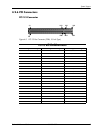
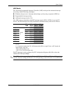
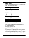
Table 4-10.
DMA Page Register Addresses
DMA Channel Page Register I/O Port
Controller 1 (byte transfers)
Ch 0
Ch 1
Ch 2
Ch 3
087h
083h
081h
082h
Controller 2 (word transfers)
Ch 4
Ch 5
Ch 6
Ch 7
n/a
08Bh
089h
08Ah
Refresh 08Fh [see note]
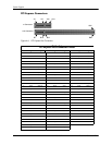
24-Bit Address—Controller 1 (Byte Transfers)
8-Bit Page Register 8-Bit DMA Controller
A23..A16 A15..A00
24-Bit Address—Controller 2 (Word Transfers)
8-Bit Page Register 16-Bit DMA Controller
A23..A17 A16..A01, (A00 = 0)