


7-16 361834-002 Technical Reference Guide
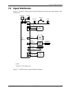
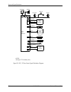
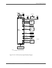
Power and Signal Distribution
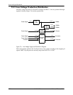
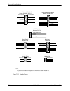
NOTE:
No polarity consideration required for connection to speaker header P6.
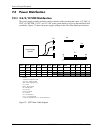
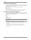
Figure 7-10. Header Pinouts
CD ROM Audio Header
1 Audio (Left Channel)
3 Ground
4 Audio (right channel)
2 Ground
CD ROM Audio
Headers P7, P11
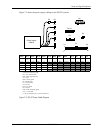
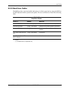
UART1 RX DATA 3
UART1 TX DATA 5
UART1 DTR 7
GND 9
4 UART1 RTS-
8 UART1 RI-
6 UART1 CTS-
10 Comm A Detect-
Serial Port A
Header P54
UART1 DCD- 1
2 UART1 DSR-
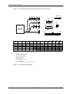
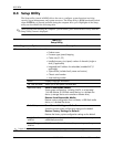
UART2 DTR- 1
UART2 CTS- 3
UART2 TX DATA 5
GND 7
+5.0V 9
2 UART2 RX DATA
4 UART2 DSR-
8 GND
6 UART2 RI-
10 +3.3V aux
UART2 RTS- 11
UART2 DCD- 13
12 Comm B Detect
+12V 15
14 -12V
Serial Port B
Header P52
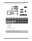
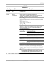
Hood Lock 1
GND 5
2 Coil Conn
4 +12V
6 Hood Unlock
Hood Lock
Header P124
1 Hood SW Detect
2 GND
3 Hood Sensor
Hood Sense
Header P125
HD LED Cathode 1
HD LED Anode 3
GND5
2 PS LED Cathode
4 PS LED Anode
8 GND
6 Pwr Btn
GND 11
Therm Diode A 13
12 NC
Chassis ID0 9
14 Therm Diode C
Power Button/LED, HD LED
Header P5 (USDT, SFF, ST)
10 Chassis ID1
HD LED Cathode 1
HD LED Anode 3
GND5
M Reset 7
+5 VDC 9
2 PS LED Cathode
4 PS LED Anode
8 GND
6 Pwr Btn
10 NC
NC 11
GND 13
12 GND
Chassis ID2 15 16 +5 VDC
Power Button/LED, HD LED
Header P5 (MT, CMT)
18 Chassis ID1Chassis ID0 17