


5-30 361834-002 Technical Reference Guide
Input/Output Interfaces
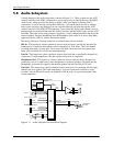
5.8 Audio Subsystem
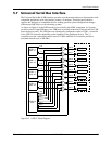
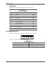
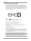
A block diagram of the audio subsystem is shown in Figure 5-11. These systems use the AC97
Audio Controller of the 82801 component to access and control an Analog Devices AD1981B
Audio Codec, which provides the analog-to-digital (ADC) and digital-to-analog (DAC)
conversions as well as mixing and equalizer functions. All control functions such as volume,
audio source selection, and sampling rate are controlled through software through the AC97
Audio Controller of the 82801 ICH component. Control data and digital audio streams (record
and playback) are transferred between the Audio Controller and the Audio Codec over the AC97
Link Bus. The codec mono analog output is applied to a single-channel amplifier that drives the
internal speaker. Plugging headphones into the Headphone jack results in an active Spkr Mute
signal used by the codec to ,silence the internal speaker
The analog interfaces allowing connection to external audio devices include:
Mic In—This input uses a three-conductor (stereo) mini-jack that is specifically designed for
connection of a condenser microphone with an impedance of 10-K ohms. This is the default
recording input after a system reset. On systems with both a front and rear microphone jack
either jack is available for use (but not simultaneously).
Line In—This input uses a three-conductor (stereo) mini-jack that is specifically designed for
connection of a high-impedance (10k-ohm) audio source such as a tape deck.
Headphones Out—This input uses a three-conductor (stereo) mini-jack that is designed for
connecting a set of 16-ohm (nom.) stereo headphones or powered speakers. Plugging into the
Headphones jack mutes the signal to the internal speaker and the Line Out jack as well.
Line Out—This output uses a three-conductor (stereo) mini-jack for connecting left and right
channel line-level signals (20-K ohm impedance). A typical connection would be to a tape
recorder's Line In (Record In) jacks, an amplifier's Line In jacks, or to powered speakers that
contain amplifiers.
Figure 5-11. Audio Subsystem Functional Block Diagram
TDA
7056
Headphones/
Line Out
(L)
(R)
HP Out Audio (L/R)
Audio
Codec
(L)
(R)
Line In
Mic In
Audio
Bias
Internal
Speaker
+
-
Mono
Audio
PC Beep Audio
AC97
Link Bus
82801 ICH
AC’97
Audio
Cntlr.
PCI
Bus
Spkr Mute
P23
P23
P6
CD Audio (L)
CD Audio (R)
CD ROM Header P7 [2]
Aux Audio (L)
Aux Audio (R)
AUX In Header P11 [1]