


Technical Reference Guide 361834-002 7-9
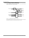
Power and Signal Distribution
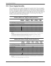
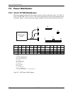
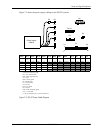
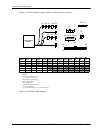
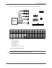
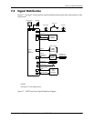
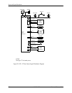
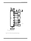
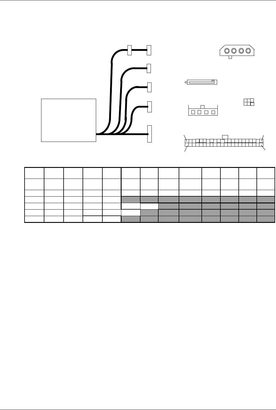
Figure 7-3 shows the power supply cabling for the SFF/ST systems.
Connectors not shown to scale.
All + and - values are VDC.
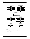
RTN = Return (signal ground)
sns = sense
GND = Power ground
RS = Remote sense
FC = Fan command
FO = Fan off
FSpd = Fan speed
FS = Fan Sink
POK = Power OK (power good)
VccP = +12 for CPU
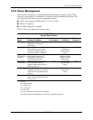
[1] This row represents pins 13–24 of connector P1
Figure 7-3. SFF/ST Power Cable Diagram
Conn Pin 1 Pin 2 Pin 3 Pin 4 Pin 5 Pin 6 Pin 7 Pin 8 Pin 9
Pin
10
Pin
11
Pin
12
P1 +5
aux
RTN + 5 +5 PS On RTN Pwr Gd +3.3 +3.3 Tach RTN Fan
P1 [1] +12 +5 sns RTN +5 +5 +3.3 RTN +3.3 sns +3.3 +3.3 RTN -12
P2 +5 RTN RTN +12
P3 RTN RTN RTN VccP VccP +12
P4, 5 +3.3 RTN +5 RTN +12
P6 +12 RTN RTN +5
Power Supply
349318
P1
P2
P3
P4
P5
P6
P1
13
1
12
P4, P5
24
1
23
4
1
23
4
5
1
2
34
P6
P3
P2