


v
Fig 6.2 Encoder Reset Connector.............................................................. 6-18
Fig 8.1 Manipulator Configuration................................................................ 8-2
Fig 8.2 Motor and Brake wiring connection No.1 ......................................... 8-3
Fig 8.3 Motor and Brake wiring connection No.2 ......................................... 8-4
Fig 8.4 Encoder wiring Connection No.1 ..................................................... 8-5
Fig 8.5 Encoder Wiring Connection No.2..................................................... 8-6
Fig 8.6 Encoder Wiring Connection No.3..................................................... 8-7
Fig 8.7 Application Wiring Connection No.1................................................. 8-8
Fig 8.8 Application Wiring Connection No.2................................................. 8-9
List of Tables
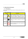
Table 1-1 Safety marking ............................................................................. 1-5
Table 1-2 State of robot stop...................................................................... 1-17
Table 2-1 Basic Specifications for Models.................................................... 2-4
Table 2-2 Axis Motion..................................................................................2-11
Table 3-1 Components name....................................................................... 3-2
Table 3-2 Allowable load weight..................................................................3-11
Table 3-3 Allowable Load Torque................................................................3-11
Table 3-4 Allowable Moment of Inertia....................................................... 3-12
Table 4-1 Inspection Schedule..................................................................... 4-2
Table 4-2 Inspection Items and Periods....................................................... 4-3
Table 4-3 Inspection part for main bolts ....................................................... 4-5
Table 6-1 Trouble phenomenon and cause.................................................. 6-3
Table 6-2 Motor Weight.............................................................................. 6-10
Table 6-3 Necessary Tools......................................................................... 6-12
Table 6-4 Necessary parts ......................................................................... 6-12
Table 6-5 Reset connectors corresponding to axes................................... 6-17
Table 6-6 Data range after resetting .......................................................... 6-20
Table 7-1 Spare Parts ListⅠ ........................................................................ 7-2
Table 7-2 Spare Parts ListⅡ ........................................................................ 7-4
Table 7-3 Spare Parts List Ⅲ ...................................................................... 7-5
Table 7-4 Spare Parts List Ⅳ ...................................................................... 7-6
Table 7-5 Spare Parts List Ⅴ ...................................................................... 7-7
Table 9-1 Materials of each part................................................................... 9-2
List of Tables