


22 RS/6000 43P 7043 Models 150 and 260 Handbook
architected interfaces and therefore have the opportunity for adding unique
value. This flexibility is achieved through architecture facilities including:
• Device drivers
• Open Firmware (OF)
• Run-Time Abstraction Services (RTAS)
• Hardware abstraction layers
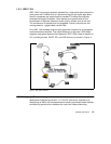
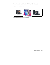
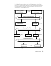
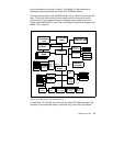
2.1.2 Platform Topology
Figure 7 on page 23 shows a general platform topology of the RS/6000
Platform Architecture. All platforms (from notebooks to high-end servers)
consist of one or more PowerPC microprocessors, a volatile system memory
separate from other subsystems, and a number of I/O devices, that may
initiate transactions to system memory.
The processors are linked over the primary processor bus/switch to each
other, to the system memory, and to one or more host bridges (host bridge 0
must be a PCI host bridge).
In general, I/O devices do not connect to the primary processor bus/switch.
The host bridges connect to secondary buses that have I/O devices
connected to them. In turn, one or more bus bridges may be employed to
tertiary buses (for instance ISA or PCI) with additional I/O devices connected
to them. Typically, the bus speeds and throughput decrease and the number
of supportable loads increases as one progresses from the primary processor
bus to more remote buses.
There are variations to this topology that are likely to occur and are therefore
worth describing in the following list. The architecture describes interfaces
not implementation. The logical software model must remain the same, even
if the physical topology is different.
• In a smaller platform, the host bridge, memory, or an I/O device may be
integrated into a single chip. In this case, the topology would not look like
Figure 7 on page 23, from a chip point of view, but, instead, would be
integrated onto the single chip.
• In a larger platform, secondary buses may be implemented, with two or
more host bridges, as two or more parallel expansion buses for
performance reasons. Similarly, tertiary buses may be two or more parallel
expansion buses off each secondary bus. This is indicated by the dots
near the host bridge and the bus bridge.