D-6 A
PPENDIX
D: T
ROUBLESHOOTING
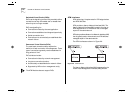
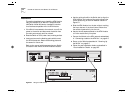
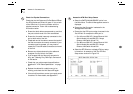
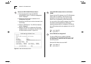
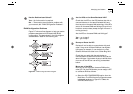
Check the Physical Connections
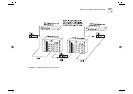
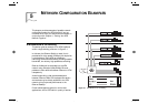
Check that the Link Status and Far End Status LEDs on
the ATM Module are ON and lit green. If one or both
of the LEDs is not lit, there is a problem with the
physical connection. Follow the troubleshooting
information below:
a
Ensure that both devices are powered-up, and that
the ports at both ends of the link are enabled.
b
Ensure that the cable is securely connected to the
port at both ends of the link.
c
Check each end of the cable to ensure that each of
the fiber connectors is correctly connected. If your
connectors can be reversed, you may need to
reverse the TX and RX cable connectors at one end
of the link.
d
Remove any objects obstructing the cable and
straighten out any kinks in the cable.
e
If you suspect that the fiber optic connector is
dirty, see “Cleaning Dirty Fiber Optic Connectors”
in this section.
f
Check that your cable meets the specifications
described in “ATM Cable Specification” on page
C-1
g
Replace the cable with a cable known to be
working, and check the Link Status LED again.
h
If there is still a problem, contact your repair center
for advice. For more details, see Appendix E.
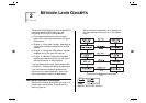
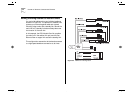
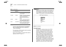
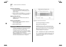
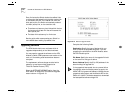
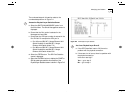
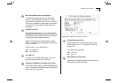
Access the ATM Port Setup Screen
a
Select the SWITCH MANAGEMENT option from
the Main Menu. The Switch Management screen is
displayed.
b
Ensure that the
Port
option is selected in the
Management Level
field.
c
Ensure that the ATM port number is entered in the
Port ID
field. For example the ATM port is:
■
Port
13
on an IBM 8271 Nways Ethernet LAN
Switch Model 612 and IBM 8271 Nways
Ethernet LAN Switch Model 712
■
Port
25
on an IBM 8271 Nways Ethernet LAN
Switch Model 624 and IBM 8271 Nways
Ethernet LAN Switch Model 524
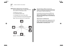
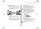
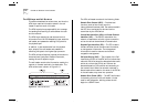
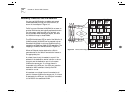
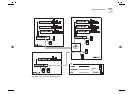
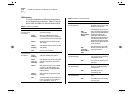
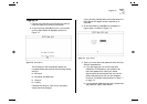
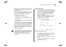
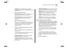
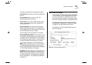
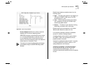
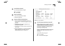
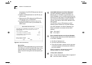
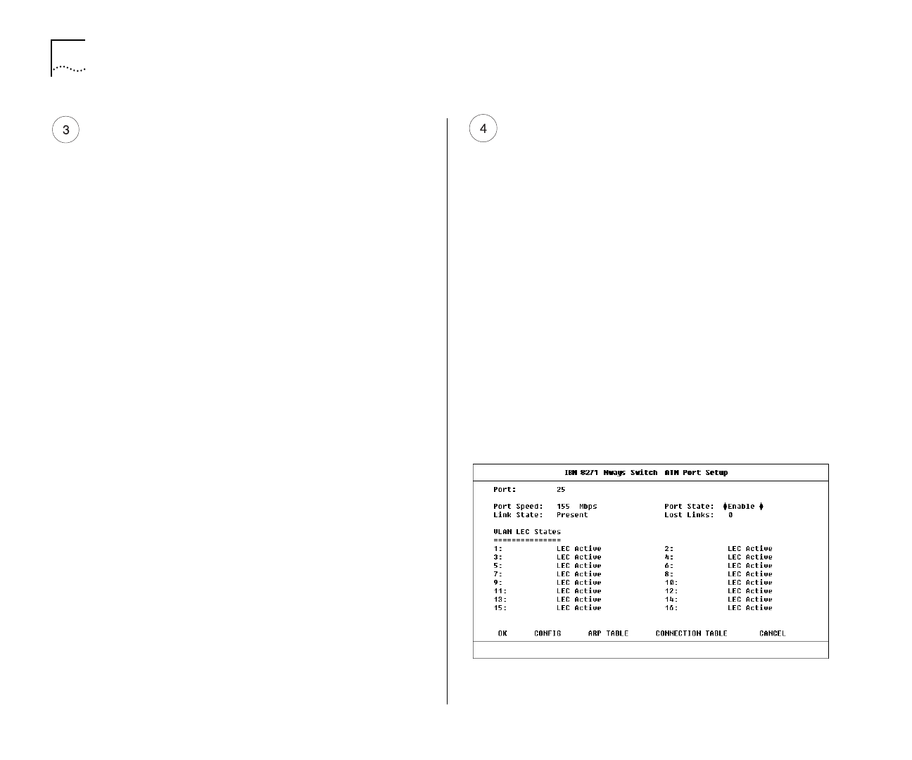
d
Select the SETUP button to display ATM port setup
information. An example of the The ATM Port
Setup screen is shown in Figure D-3.
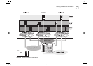
Figure D-3
ATM Port Setup Screen