8-8 C
HAPTER
8: M
ANAGING
THE
ATM M
ODULE
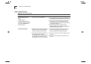
Lost Links
The number of times a link was unable to
transmit traffic, that is, the number of times (since the
device was reset) that the
Link State
became
Not
Available
.
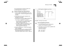
LEC States
Shows the status of the LEC for each
VLAN. The state can be:
LEC Active
— traffic is passing through the LEC.
LEC Inactive
— traffic is not passing through the LEC.
LEC Not in Use
— you have decided not to connect
this VLAN to the ATM network. The VLAN may still be
in operation within the Switch.
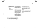
CONFIG
This button takes you to the ATM Module
Configuration screen, which allows you to monitor
and set the standards used by the ATM Module to
communicate with other ATM devices.
The ATM Module Configuration screen is described in
“Configuring an ATM Port” on page 8-2.
ARP TABLE
This button takes you to the ARP Table
screen, which allows you to displays the ATM and
MAC addresses on remote devices. The ARP Table
screen is described in “Mapping Far End MAC
Addresses” on this page.
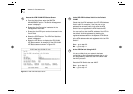
CONNECTION TABLE
This button takes you to the
ATM Connection Table screen, which allows you to
display ATM connection details. The ATM Connection
Table is described in “Displaying an ATM Connection”
on page 8-10.
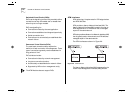
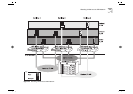
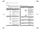
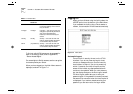
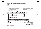
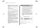
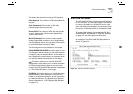
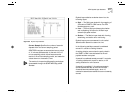
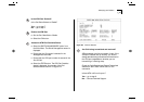
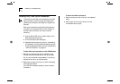
Mapping Far End MAC Addresses
To communicate with a device, the software must be
able to map the MAC address of the destination
device to the destination edge-device’s ATM address.
This mapping is normally performed by the LEC, and
for the vast majority of devices you do not need to
map MAC addresses to ATM addresses.
The MAC address and ATM address mappings are
stored in the LAN Emulation
ARP Table
(which should
not be confused with the IP ARP Table).
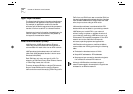
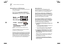
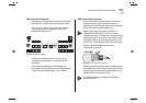
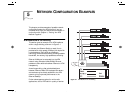
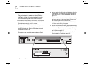
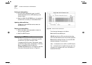
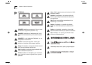
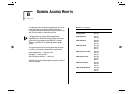
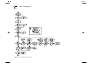
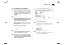
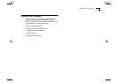
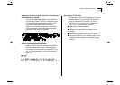
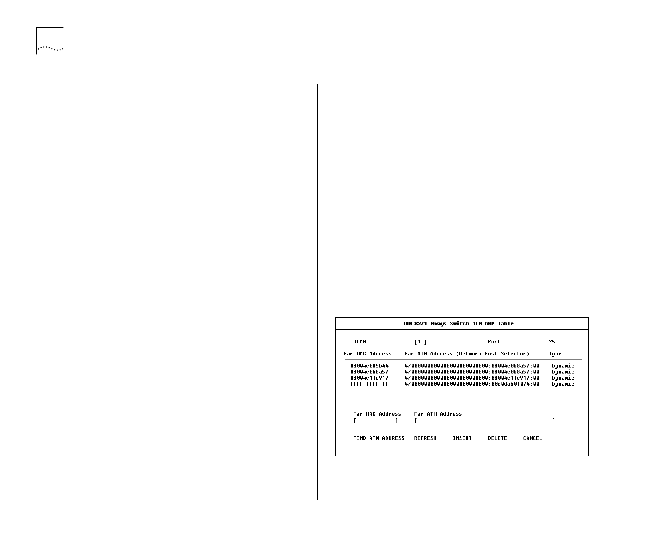
To access the ATM ARP Table screen access the ATM
Port Setup screen, as described in “ATM Port Setup”
on page 8-6, and then select the ARP TABLE button.
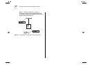
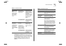
An example of the ATM ARP Table screen is shown in
Figure 8-8.
Figure 8-8
ATM ARP Table Screen