Post-Installation Checks 6-5
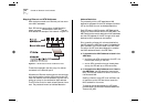
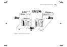
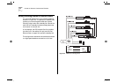
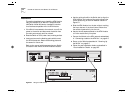
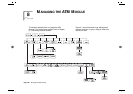
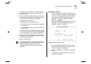
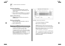
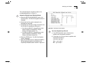
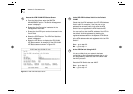
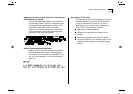
Connecting a cable to the ATM Port
1
Ensure that the cable you wish to connect to the port
meets the correct specification. For cable
specifications, refer to “ATM Cable Specification” on
page C-1.
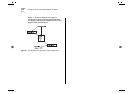
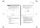
2
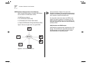
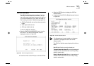
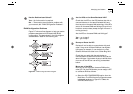
Each end of the fiber cable has a transmit (Tx) and
receive (Rx) connector. Connect the Rx connector to
the port’s Tx socket. Connect the Tx connector to the
port’s Rx socket. Do the same at the other end of the
connection.
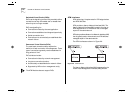
Powering Up the Switch
The Switch does not have an On/Off button, so the
only way to power up the Switch is to connect it to
the main power supply using a power cable.
Connecting a power supply and safety information is
described in the user guide that accompanies your
Switch.
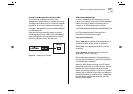
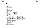
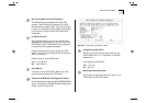
Power On Self Test (POST)
When powered up, the Switch and ATM Module
enter a
Power On Self Test (POST)
. The type of tests
performed depend on how POST has been configured
for the Switch. Two types of POST are available:
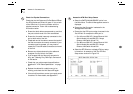
■
Normal POST
— a basic confidence check which
takes between 10 and 20 seconds to complete, and
includes:
■
Checksum tests of boot and system areas of
Flash
memory.
■
System memory tests.
■
MAC address verification test.
■
System timer test.
■
CAM (Contents Addressable Memory)
tests.
■
Console Port tests.
■
Internal packet forwarding tests.
■
Switch and ATM Module
ASIC (Application
Specific Integrated Circuit)
tests.
■
Switch and ATM Module ASIC memory tests.
■
ATM Module interface tests.
■
ATM Module packet forwarding tests.
■
Extended POST
— more extensive testing which
takes between 50 and 225 seconds to complete
and includes all of the
Normal POST
tests plus more
extensive system memory and ASIC memory tests.
When a new Switch is powered-up for the first time, it
performs a
Normal POST
, which is the default setting.
If you suspect that there is a problem with your device
which has not been detected by the
Normal POST
, run
the
Extended POST
. Configuring POST is described in
the user guide that accompanies your Switch.
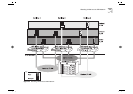
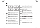
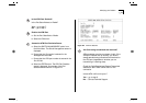
The LEDs used to indicate POST failure and other
post-installation checks are described in
“Post-Installation Checks”.
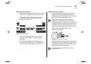
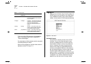
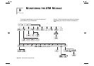
Post-Installation Checks
This section describes the LEDs and basic checks that
you can use to verify your installation, and to ensure
that the Switch and ATM Module are operating
correctly.