


Configuring an ATM Port 8-3
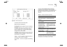
SONET/SDH
Specifies the framing used. Select either
SONET STS-3c
or
SDH STM-1
. The default is
SONET
STS-3c.
The
MAX VPI Bits
and
MAX VCI Bits
fields described
below, are used to determine how many bits can be
used within each cell header to define the value of
the VPI and VCI. The value of the VPI and VCI fields
identify the connection.
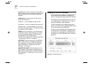
MAX VPI Bits can be used to identify which WAN
connection to use. If you have several remote sites
(London, Manchester and Leeds) you can specify a
unique VPI value which identifies traffic going to that
site. For example, the VPI value for London could be = 1,
Manchester could be = 2, and Leeds could be = 3.
There are 11 bits available to be shared between the
VPI and VCI. The default is 3 VPI bits and 8 VCI bits.
You should not normally need to change the default
settings. The adjacent ATM Switch can read the
settings of these fields via ILMI and normally
negotiates with the devices to use the lowest common
denominator. If the ATM Switch is non-standard, you
may need to amend the
MAX VPI Bits (0–4)
field.
MAX VPI Bits (0
–
4)
Shows the number of bits available
in the cell header that can be used to determine the
value of the VPI. Up to 4 bits are available for use. The
number of bits set offers a range of possible values for
the VPI (as shown within Table 8-1).
Max VCI Bits
The number of bits available for the
VCI is calculated automatically, using the following
equation:
MAX VCI Bits = (11 minus the value of Max VPI Bits)
ILMI VCC
This number identifies the connection used
for
Interim Local Management Interface (ILMI)
requests.
The first field identifies the
Virtual Path
and the second
field identifies the
Virtual Channel
.
You should only change the ILMI VCC if the ATM
switch connected to ATM Module does not use the
default ILMI VCC (VPI = 0, VCI = 16).
VCC connections with values 0 (zero) to 31 are
reserved for standard connections and you should
avoid using these values wherever possible.
Hardware Version
Shows the version number of the
ATM Module hardware.
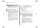
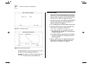
Table 8-1
VPI and Bit Settings
Desired Value of VPI Number of bits
required
00
0 or 1 1
within the range 0
–
32
within the range 0
–
7 3 (default)
within the range 0
–
15 4