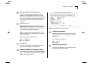
Asynchronous Transfer Mode (ATM) Layer 2-13
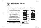
Interim Local Management Interface (ILMI)
The ATM Forum produced the
Interim Local
Management Interface (ILMI)
to increase monitoring
and diagnostic facilities, and to provide ATM address
registration at the
User-to-Network Interface (UNI)
.
ILMI uses a
Management Information Base (MIB)
and
the
SNMP
protocol.
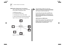
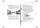
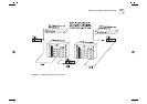
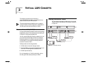
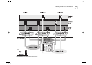
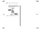
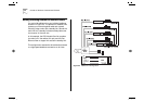
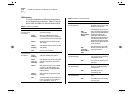
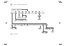
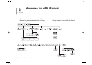
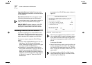
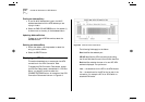
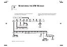
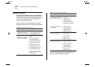
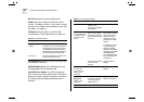
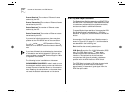
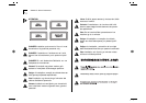
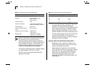
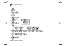
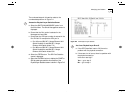
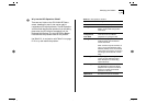
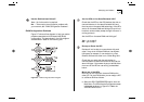
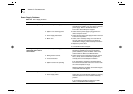
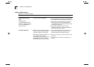
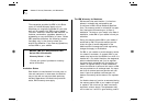
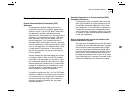
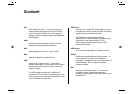
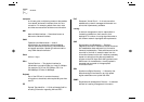
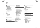
Each device that provides ILMI support contains a
UNI Management Entity (UME)
, which uses SNMP to
access management information stored in the ILMI
MIB of the adjacent switch, see Figure 2-9.
Figure 2-9
UNI Management Entities
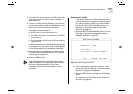
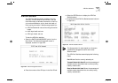
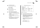
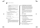
ATM Address Registration
In order to establish an ATM connection, both the
user and the network must know the ATM addresses
used at that
User-to-Network Interface (UNI)
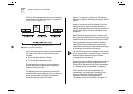
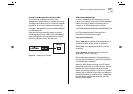
. An
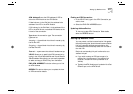
example of an ATM address is shown below.
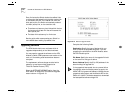
47007900000000000000000000:00A03E000001:00
An ATM address consists of three sections of
information and is 20 bytes in length:
network:host:identifier
Where
network
is a network prefix assigned to the
device by the ATM Switch, and is 13 bytes long.
Where
host
is the edge-device identifier, and is 6
bytes long.
Where
identifier
identifies the client within the
edge-device, and is 1 byte long.
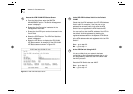
ILMI provides a mechanism for the edge-device (in
this case the ATM Module) to inform the ATM Switch
of the addresses it represents.
When the ATM Module initializes, the ATM Switch
sends a network prefix to the ATM Module. The ATM
Module then tries to register itself with the ATM
Switch by attaching the prefix to the front of its MAC
address, and an identifier to the end of the address. It
then sends this back to the ATM switch. If acceptable,
the ATM Switch registers the address as the ATM
Module’s ATM address.